Forums
|
Forums >> Revit Structure >> Technical Support >> Upturned Beams in RST 2010
|
|
|
active
Joined: Thu, Oct 29, 2009
32 Posts
No Rating |
So I'm on my 2nd week of RST 2010 and I've been going through tutorials, forums, YouTube videos, etc. I believe I've got a pretty good grasp of a lot of the workings but I'm struggling with creating a family for Upturned Beams/Moment Frames/Transfer Beams  Whatever you'd like to call them). I've been trying to modify the beam family template provided with no luck. The beam continues to snap to the bottom of the deck rather than the top even after I've moved the sweep path, and the profile with respect to the reference level; the height parameter is not working though it did when I used an extrusion rather than a sweep, I've checked the material to make sure that the elements join but nothing seems to be working correctly. Obviously I have very little experience with creating new families but I wondered if anyone could point me in the right direction, maybe give me a few pointers. I've been creating the beam using the sweep command. I used the extrude before and while all the flexing worked great, the beam did not snap from column to column but rather to the default length of 10'. I've attached the file for your viewign pleasure though I'm sure it's lacking. Thanks a million. Whatever you'd like to call them). I've been trying to modify the beam family template provided with no luck. The beam continues to snap to the bottom of the deck rather than the top even after I've moved the sweep path, and the profile with respect to the reference level; the height parameter is not working though it did when I used an extrusion rather than a sweep, I've checked the material to make sure that the elements join but nothing seems to be working correctly. Obviously I have very little experience with creating new families but I wondered if anyone could point me in the right direction, maybe give me a few pointers. I've been creating the beam using the sweep command. I used the extrude before and while all the flexing worked great, the beam did not snap from column to column but rather to the default length of 10'. I've attached the file for your viewign pleasure though I'm sure it's lacking. Thanks a million. Kris
-----------------------------------
Kris Runung
Project Manager/Engineer
McClone Construction Co
Wheat Ridge, CO 80033 |
This user is offline |
|
 | |
|
|
active
Joined: Wed, Mar 12, 2008
322 Posts
 |
Unfortunately, I do not have Revit 2010 and cannot view your file. It would also be helpful to see a sketch of the intention and a screenshot of the problem. At any rate, it sound like you are attempting to place a steel beam on the top of steel deck. Or, perhaps you are working with concrete. Not really sure. This would be helpful info too. Here's a few ideas. 1. Use the out-of-the-box Revit family, and create a new reference level for the bottom of the beam. Not sure how many beams you have, or if their elevation varies throughout the project. If you have a consistent elevation you can use- wheter it's top of beam or bottom of beam, create a reference level for that so you can constrain your framing to that level. If you are using a bottom of beam reference elevation- you can rotate the member 180° through the element properties box. 2. Use in-place families. Analytical lines can be added as necessary if you are using them. Make sense?
|
This user is offline |
|
|
|
active
Joined: Thu, Oct 29, 2009
32 Posts
No Rating |
So I tried to create the reference plane that I assigned the "Bottom" and nothing seemed to change. I have included some pictures of the family I tried to create. The beam is cast in place concrete. There are quite a few different beams at different elevations with some of them sloping up a ramp of a parking garage. I assume the easiest way would be to create a beam family to represent the case in question though I'm haveing no luck. The last picture in an example of what happens when I create the family using the extrude function. All of the constraints ork except for the fact that it does not reach column to column and that it is on the underside of the slab. Using the sweep fucntion, the beam reaches from column to column, but still underneath the slab and now the beam height and top slope are inoperable. I wonder if it as something to do with the way that I am drawing it. I'm not sure. Very frustrating. I'm not sure if I have provided anything of value but any thoughts or ideas at all would be very greatly appreciated. Thank you.
-----------------------------------
Kris Runung
Project Manager/Engineer
McClone Construction Co
Wheat Ridge, CO 80033 |
This user is offline |
|
|
|
active
Joined: Wed, Mar 12, 2008
322 Posts
|
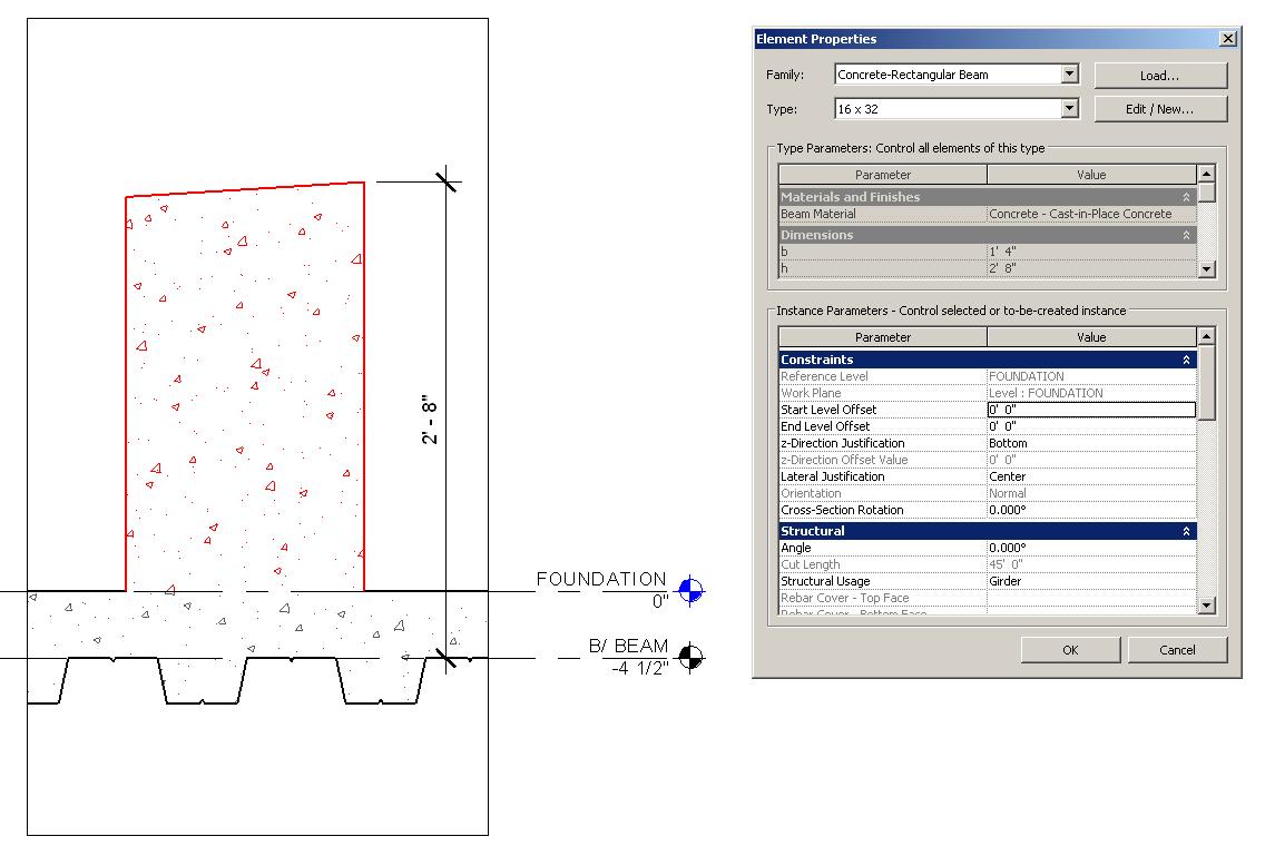
Is this what you are trying to achieve? See attached image.
|
This user is offline |
|
|
|
active
Joined: Thu, Oct 29, 2009
32 Posts
No Rating |
Yeah it seems like it. I obviously don't know which parameters you have in that family in order to create or modify that beam. I was hoping to be able to adjust the width, height, and top slope. The main thing that was frustrating me was the fact that everytime I used 3D snap to place the beam (or even in plan view), it always inserted in the -Z direction, as though the placement axis was along the top of the beam, rather than along the bottom of the beam. Not sure if that makes sense. Either way, that seems like it coincides with what was my ultimate goal. How did you manage that? Thanks, Kris
-----------------------------------
Kris Runung
Project Manager/Engineer
McClone Construction Co
Wheat Ridge, CO 80033 |
This user is offline |
|
|
|
active
Joined: Wed, Mar 12, 2008
322 Posts
|
I used the out-of-the-box concrete beam family and modified it. Not sure what problems you are having with the family you created, or the reason you are having these problems. I'd like to help you with that, but I don't have 2010. I've attached my family to this e-mail. Let me know if you don't understand it. I've also added a control which will allow you to flip the beam to make sure the top of the beam slopes in the correct direction. Set the z-direction justification to 'bottom'. See previous screenshot I've posted. Let me know if you have further troubles.
|
This user is offline |
|
|
|
active
Joined: Thu, Oct 29, 2009
32 Posts
No Rating |
This is what I found that I had to do when I created the faulty beam. It always located itself below the slab. I found the Z-direction Justification pulldown at that point and that at least got it to the correct side of the slab. Is there anyway to save that setting that you know of so that when I pull this family in, it will automatically have "Bottom" as the justification? Thank you very much btw. Just curious, did you create the beam with an extrusion or a sweep? Or neither? Thanks Again Kris
-----------------------------------
Kris Runung
Project Manager/Engineer
McClone Construction Co
Wheat Ridge, CO 80033 |
This user is offline |
|
|
|
active
Joined: Wed, Mar 12, 2008
322 Posts
|
I'm not sure if you are able to default the z-justification. Using the create similar command is useful for doing this type of thing, but it doesn't overide the z-justification. I used a sweep- which was what the out-of-box version used. What you are dealing with is similar to the pan and joist family within Revit. Ther problem with your family can be seen in the cross-section of the image you've posted in this thread. You've included the beam extrusion in your slab thickness. You had the right idea...
|
This user is offline |
|
|
|
Similar Threads |
|
Revit TotD – 2.22.10 | Save the trees, use DWF Markups! |
Revit Building >> Tips & Tricks
|
Mon, Feb 22, 2010 at 9:39:08 AM
|
0
|
|
Revit Crashes at Startup |
Revit Building >> Technical Support
|
Tue, Apr 27, 2010 at 6:53:45 AM
|
1
|
|
Revit TotD - Linked Model Visibility, part 1 |
Revit Building >> Tips & Tricks
|
Mon, Feb 15, 2010 at 9:08:56 AM
|
0
|
|
Revit TotD - 8.23.2010 | Section Perspectives |
Revit Building >> Tips & Tricks
|
Wed, Jan 11, 2017 at 10:26:56 AM
|
3
|
|
Revit TotD – 1.25.10 | Profile Origins and Wall Openings |
Revit Building >> Tips & Tricks
|
Mon, Jan 25, 2010 at 12:23:57 AM
|
0
|
|
|
Site Stats
Members: | 2161655 | Objects: | 23325 | Forum Posts: | 152479 | Job Listings: | 3 |
|