|
|
|
Home | Forums |
Downloads | Gallery |
News & Articles | Resources |
Jobs | FAQ |
| Join |
Welcome !
|
6 Users Online (4 Members):
Show Users Online
- Most ever was 626 - Mon, Jan 12, 2015 at 2:00:17 PM |
Forums
|
Forums >> Revit Building >> Technical Support >> Modeling Topograpghy
|
|
|
active
Joined: Wed, Mar 6, 2013
0 Posts
No Rating |
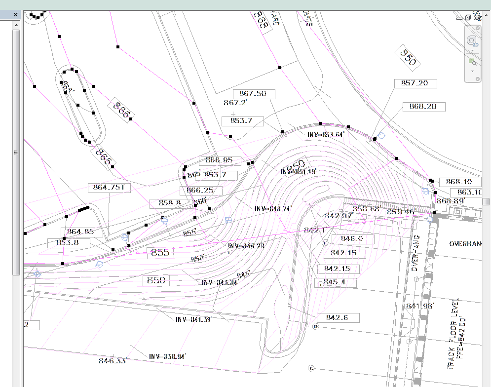
I'm testing the waters with topography in revit for structural retaining walls. I have modeled the high and low grade. I cannot get the perimeter boundary of the topography on the high grade to follow the profile of the retaining wall. On the low side of the wall the profile will not follow the concrete stair.
Below are screen shot showing where the point elevations are in plan view and a 3D view of the model.
I am using Revit 2017.
Thanks in advance for any help!
Edited on: Tue, Apr 4, 2017 at 8:32:23 AM
Edited on: Tue, Apr 4, 2017 at 8:33:52 AM
|
This user is offline |
|
 | |
|
|
site moderator|||
Joined: Tue, May 16, 2006
13079 Posts
 |
Try placing two points at every location, one on the low grade side of the wall (low number) and one on the high grade side (high number).
|
This user is offline |
|
|
|
active

Joined: Fri, Apr 7, 2017
0 Posts
No Rating |
Yeah we have to do this quite regularly working from other surveyors DTM, we tend to find Revit creates spikes when inserting ground leveldata and it looks terrible around retaining walls. As WWHub says, you need to place 2 points at adjacent sides of the walls top and bottom levels. You'll likely need to repeat this quite regularly along the length of the walls to stop the topo jumping to other closer points away from the wall. We find that if you reduce the contour distance in site properties down to 500mm the irregularities show much clearer in plan and are easier to spot, edit and adjust.
Hope this helps.
-----------------------------------
James Pegg
Managing Director / Revit Technician
Please visit our website for Laser Scanning and Point Cloud to BIM Services |
This user is offline |
View Website
|
|
|
active
Joined: Wed, Aug 28, 2013
0 Posts
 |
When i do such things such as this, i usually split the surface on both sides of the wall, whether that helps your case or not.
|
This user is offline |
View Website
|
|
|
active
Joined: Wed, Mar 6, 2013
0 Posts
No Rating |
Thanks for all the help!
|
This user is offline |
|
|
|
Similar Threads |
|
Modeling a family outside of Revit |
Revit Building >> Technical Support
|
Mon, Dec 19, 2005 at 11:39:34 PM
|
3
|
|
Show phases of modeling |
Revit Systems >> Technical Support
|
Tue, May 9, 2017 at 4:13:36 PM
|
1
|
|
how to modeling this project? |
Revit Building >> Technical Support
|
Sat, May 17, 2014 at 3:20:39 AM
|
1
|
|
Revit modeling services provided [ 1 2 ] |
Community >> The Studio
|
Sat, Jun 27, 2009 at 3:13:55 AM
|
16
|
|
Modeling a bathroom Mirror? |
Community >> Newbies
|
Mon, Jan 9, 2023 at 7:28:43 AM
|
7
|
|
|
Site Stats
Members: | 2161655 | Objects: | 23325 | Forum Posts: | 152479 | Job Listings: | 3 |
|