|
|
|
Home | Forums |
Downloads | Gallery |
News & Articles | Resources |
Jobs | FAQ |
| Join |
Welcome !
|
7 Users Online (5 Members):
Show Users Online
- Most ever was 626 - Mon, Jan 12, 2015 at 2:00:17 PM |
Forums
|
Forums >> Revit Building >> Technical Support >> Revit Walls LOD 400 or 500
|
|
|
active
Joined: Wed, Nov 16, 2011
6 Posts
No Rating |
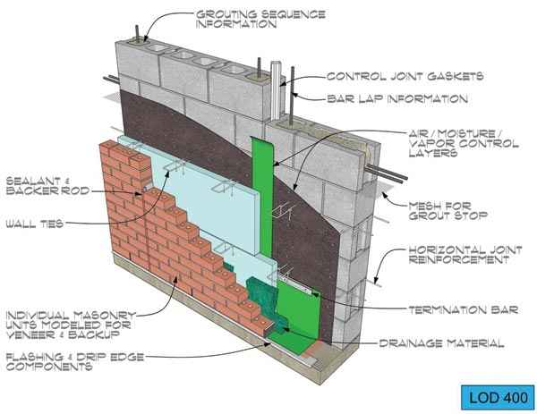
Hi, I know that Revit is designed to do LOD 400 for shop drawings or even as built drawing with LOD 500, but what is the best practice to draw walls like in the attached image, with all details, even if I have metal stud behind an internal finishes, is it an option to draw some finishes in a separate wall and locate it in place, if answer is yes, how we will deal with windows & other openings, also how can we control the thickness of the wrapping finishes at inserts or at the ends, the command (Cut Profile) from view tab is not so good to be an option for shop drawings, what to do if I want to wrap structure layer in the wall with a certain thickness? & a lot of other similar questions especially related to walls.
I hope to get an answer from some experts in this regard.
Thanks in advance.
|
This user is offline |
|
 | |
|
|
site moderator|||
Joined: Tue, May 16, 2006
13079 Posts
 |
I would draw that wall as one type with all layers.
I don't know what you mean by: "with all details, even if I have metal stud behind an internal finishes". Yes, with all layers - there are no details here, just wall layers that are material typed. Obviously, the wall shown starts at the footer and the type might change at the floor line if there is interior furring and finishes. But that is another wall type - the fdn wall would end and this would be above it.
When we have an interior finish that is only partial height like a tile wainscot, we do a thin venner wall - only tile - that is placed against the main wall. The main wall hosts all doors and windows. When you then join this inner wall to the main wall, the doors and windows will cut both walls as required.
You can use Revit Parts to do a 3D view like you show but elements like the brick anchors would not typically be in the overall project and are not in the wall types.
Door and window wrapping at jambs can be controlled in the family and wall type settings. I don't understand why cut profile doesn't work for shop drawing.
Edited on: Thu, Sep 8, 2016 at 8:46:58 AM
|
This user is offline |
|
|
|
Similar Threads |
|
Structural Steel Connections in Revit for LOD 400 models |
Workflow & Implementation >> API & Third Party Apps
|
Tue, Jul 2, 2013 at 6:15:33 AM
|
4
|
|
BIM LOD |
General Discussion >> Revit Project Management
|
Mon, Apr 18, 2011 at 2:15:04 PM
|
3
|
|
LOD (level of development)??? Anyone know what this means? |
General Discussion >> Revit Project Management
|
Mon, Oct 5, 2009 at 3:16:39 PM
|
2
|
|
LoI Details |
General Discussion >> Revit Project Management
|
Sun, Jul 14, 2019 at 1:53:06 AM
|
0
|
|
LOD Spec for Proposals |
General Discussion >> Revit Project Management
|
Tue, Oct 13, 2015 at 8:19:25 PM
|
0
|
|
|
Site Stats
Members: | 2161655 | Objects: | 23325 | Forum Posts: | 152479 | Job Listings: | 3 |
|