|
Forums >> Revit Building >> Technical Support >> Rotating Roofs
|
|
|
active
Joined: Mon, Jun 30, 2003
2 Posts
No Rating |
Using Revit Architecture 2015
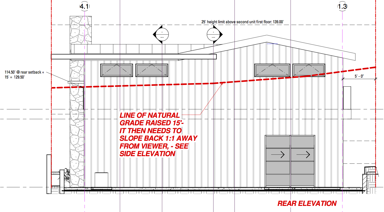
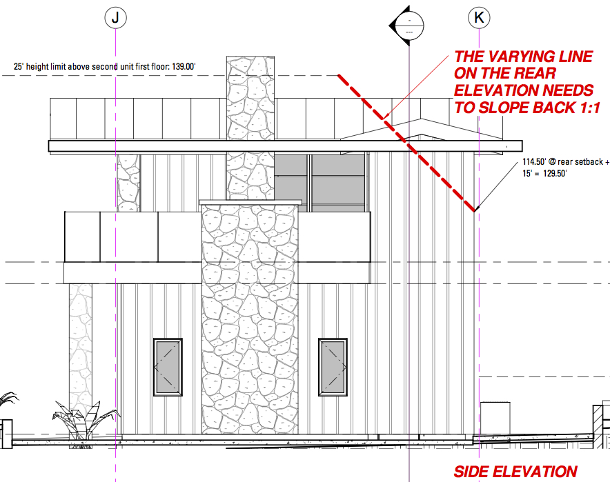
I have modeled a small building with intersecting gable roofs. It conforms to the town main height limit, but it intrudes into a secondary height limit/setback which is defined as follows: at the required rear setback line, I need to project the site slope along that line 15' into the air. The rear elevation of the building, which is right on the setback line, can be no higher than this. In my case this line is 3 connected sloping straight lines that are around 2 to 3 in 12 slope. From this setback toward the interior of the lot, the allowable building envelope rises perpendicular to the rear setback envelope that I described at 1:1, or a 45 deg. angle.
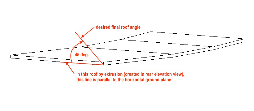
In order to re-shape my building to fit under this, I thought I would create a Revit roof as a shell to represent the height limit in 3D. I started by drawing the 3 segment sloping line and doing a roof by extrusion, which resulted in a pitched roof following these slopes but with horizontal ridges and valleys instead of sloped ones. I thought I would then go to a side view and rotate it 45 deg., or try to specify a 12:12 roof slope along the edge at the back wall. Revit gives me a "you can't do that" message with no further explanation. Same response when I try Roof by Footprint, Face, or if I try to use a Mass. Any ideas on how to model this? Thanks!
|
This user is offline |
|
 |
|
|
|
active
Joined: Sun, Jun 14, 2009
68 Posts
 |
a picture tells a 1000 words, how about posting a 2d detail explaining it all?
|
This user is offline |
|
|
|
site moderator|||
Joined: Tue, May 16, 2006
13079 Posts
|
Way too complicated too read and understand. You should have done a sketch showing the requirements.
|
This user is offline |
|
|
|
active
Joined: Mon, Jun 30, 2003
2 Posts
No Rating |
Here are two elevations annotated to illustrate my question above:
|
This user is offline |
|
|
|
site moderator|||
Joined: Tue, May 16, 2006
13079 Posts
|
I don't understand. From your second image, the structure appears to be too tall already and this view shows the limit. Why complicate this when sctions will work.
Or just do a single roof plane for each side.
Edited on: Tue, Feb 23, 2016 at 3:29:26 PM
|
This user is offline |
|
|
|
active
Joined: Mon, Jun 30, 2003
2 Posts
No Rating |
I can't cut study sections until I create the height envelope in 3D because it slopes in two directions. I am attaching a 3D screen shot of my progress object. I hope it helps you understand.
Edited on: Tue, Feb 23, 2016 at 4:33:04 PM
|
This user is offline |
|
|
|
active
Joined: Mon, Jun 30, 2003
2 Posts
No Rating |
I can't cut study sections until I create the height envelope in 3D because it slopes in two directions. I am attaching a 3D screen shot of my progress object. I hope it helps you understand. PLEASE DELETE THIS DOUBLE POST (SAME AS #6 ABOVE), I COULDN'T SEE HOW.
Edited on: Tue, Feb 23, 2016 at 4:32:20 PM
Edited on: Tue, Feb 23, 2016 at 4:33:46 PM
Edited on: Tue, Feb 23, 2016 at 7:55:12 PM
|
This user is offline |
|
|
|
active
Joined: Sun, Jun 14, 2009
68 Posts
|
why not treat the envelope you want to create as a series of very thin roofs on 45 deg pitch- 1 for each slope plane as shown in your sketch.
where the roofs intersect , trim them and then join them.
then assign them as a semi transparent material so you can more easily see where your proposed model roof will intersect these.
in other words rather than trying to make this envelope thing in 1 go, make it 3 separate pieces and join/group.
hope this helps.
|
This user is offline |
|
|
|
active
Joined: Mon, Jun 30, 2003
2 Posts
No Rating |
Thanks for the reply. I understand what you are saying as far as the final object, but don't know how to this step: In creating the first of 3 rectuangular planes, how do I get it to slope in two directions?
Thanks!
|
This user is offline |
|
|
|
active
Joined: Mon, Aug 6, 2012
0 Posts
 |
David, I feel your frustration. I am frustrated too trying to figure out what you can’t do exactly. May I ask: Can you visualize and sketch on a piece of paper what you want? If so: then maybe you could post that sketch so we can see your vision. An isometric sketch would help us to help you.
|
This user is offline |
|
|
|
|
|
active
Joined: Mon, Jun 30, 2003
2 Posts
No Rating |
Bartholemew,
I did attach an annotated isometric sketch in post #6 above, please take a look.
|
This user is offline |
|
|
|
active
Joined: Mon, Aug 6, 2012
0 Posts
|
Yes, I saw that David. Thanks. What I think would be more helpful is to see what you visualize it should look like. You want to get Revit to "reshape" the image in post#6 to look like what?
|
This user is offline |
|
|
|
active

Joined: Tue, Aug 25, 2009
0 Posts
|
I may be completely misunderstanding everythign here... but... why not use a model in place component. It seems like you could just sketch each shape and extrude them. Join them, crate voids to hack away parts. You already have your work planes based on the roof, and the lines on the elevation right?
|
This user is offline |
View Website
|
|
|
active
Joined: Mon, Aug 6, 2012
0 Posts
|
Might be easier to just go the City and ask for a variance. Ha! Sorry, couldn't help myself.
Edit: David, have you tried using a floor instead of a roof? By doing so, you can use Modify Sub Elements to sculpt the shape your looking for - if it is a shape your after. Still unclear on that however.
Edited on: Wed, Feb 24, 2016 at 11:37:03 AM
|
This user is offline |
|
|
|
active
Joined: Mon, Aug 6, 2012
0 Posts
|
It just occurred to me what you’re trying to do: a 3D tent or envelope like is shown in this attachment. I suspect your modifying for reuse an existing product. Am I right? Anyways – use the method I described above: Floor-Modify Sub Elements.
|
This user is offline |
|
|
|