|
Forums >> Revit Structure >> Technical Support >> placing beams
|
|
|
active
Joined: Mon, Mar 30, 2015
0 Posts
No Rating |
So I have a very simple project but I am stumped on placing the joists.
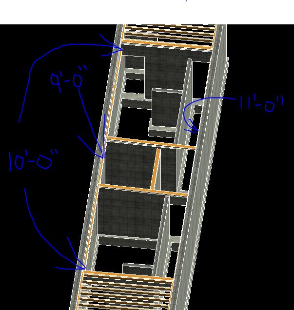
I have a simple one story rectangular structure. The roof joists are 2x10's at 16" o.c. and bear on 4x10 ledgers along each wall.
One ledger is at a fixed height. On the opposite wall, the ledgers slope down to the middle, so that they are higher on the ends and all the drainage goes down to the middle.
I have placed reference planes, named them, and I have the ledgers in place.
I just need to know some more terminology or something because I cannot see the reference planes in the roof plan and I don't really know where to start.
Any help would be great and I'll leave out the part about how frustrated I am 
|
This user is offline |
|
 |
|
|
|
active

Joined: Thu, Mar 17, 2005
1231 Posts
 |
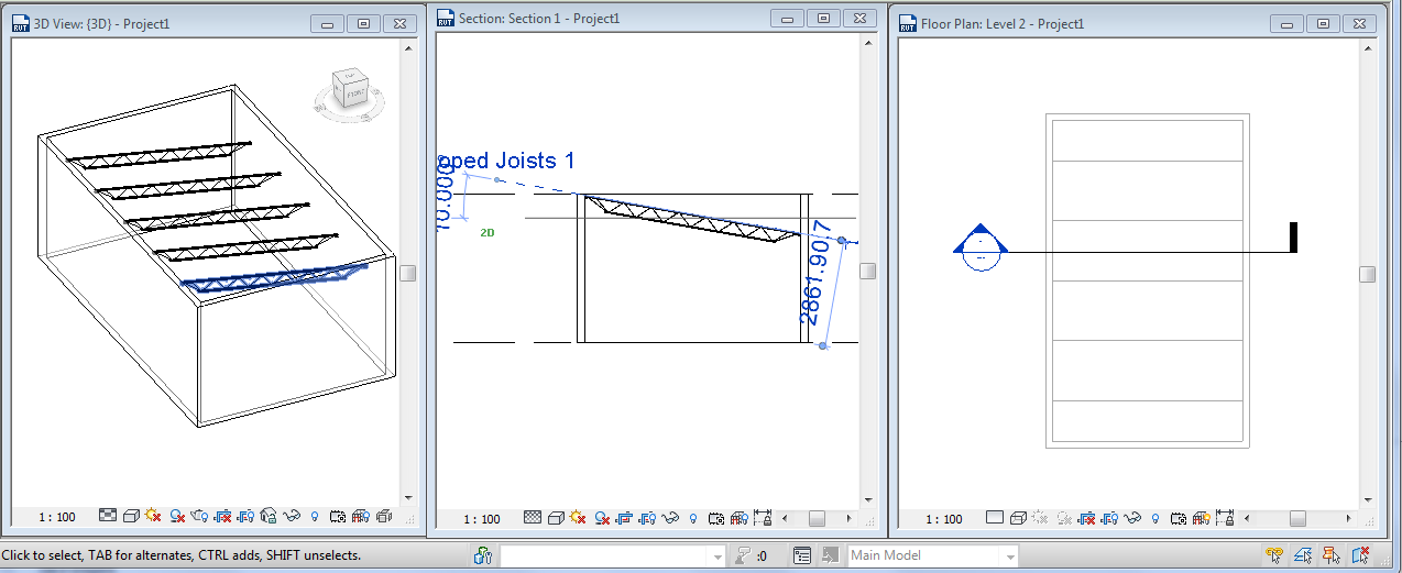
I'm not 100% sure exactly where you want the slopes but in summary you would create the reference plane * and give it a Name in a view perpendicular to the slope (section or elevation view) then in the plan view make that reference plane 'your current workplane' and then draw the sloped joists in that plan view. You won't actually see the refernce plane in the plan view but as long as it's the current 'workplane' then the joists will slope along that named reference plane. See image below where I use an OWSJ instead of a 2x10 and I also used a Beam System and sketch the system perimeter by tracing around the walls with the rectangle tool.
-----------------------------------
.
FULL 'DOWNLOAD ACCESS' to all 850+ CADclips videos for only $150
|
This user is offline |
View Website
|
|
|
active
Joined: Mon, Mar 30, 2015
0 Posts
No Rating |
I guess I want to know what the "pick supports" button is in the beam system sketch mode. Because the slope is different for each joist. One support slopes and the other is at a fixed elevation. So it's sort of a twisted roof really. But this is a small structure and not complicated at all.
So I "pick supports" in the beam system sketch mode and it does not use the supports I pick. In fact, it slopes everything the opposite way and I want to know why.
I would rather just pick supports and have the joists bear on those supports than having to create "reference planes" in different views etc.
|
This user is offline |
|
|
|
active
Joined: Thu, Mar 17, 2005
1231 Posts
|
Make sure the [3D] option is selected / activated on the options bar when picking the supports.
-----------------------------------
.
FULL 'DOWNLOAD ACCESS' to all 850+ CADclips videos for only $150
|
This user is offline |
View Website
|
|
|
active
Joined: Mon, Mar 30, 2015
0 Posts
No Rating |
Right but there's no option for 3D snapping when doing a Beam System. there is for one beam at a time of course. but for beam system, there is none.
I would think that "Pick supports" means 3D at the very least anyway. But I just saw that "pick supports" means pick existing members to draw the boundary line and has nothing to do with actually supporting the beams.
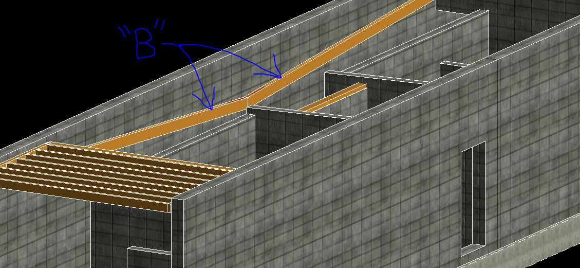
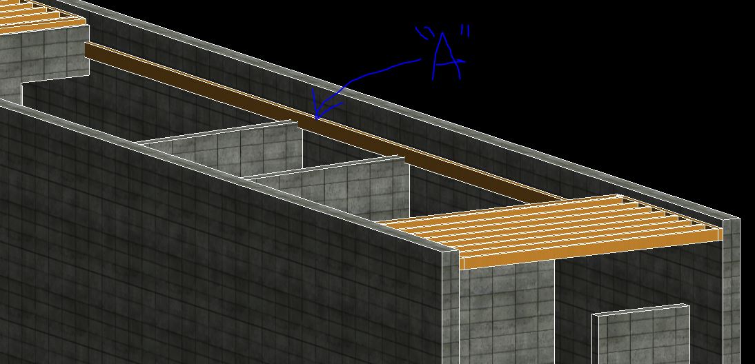
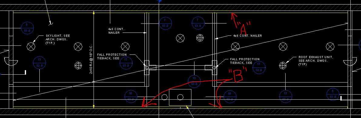
so the new screenshots show that the beam system has to span between the two sides of the building and I labeled the supports "A" and "B"
It's really simple, I just cannot get a good 3D shot that shows both supports simultaneously. so where do I create a reference plane or a working plane? Why can't the ledger beam be my support so that if I change the elevation or slope, the beams will still bear upon it?
|
This user is offline |
|
|
|
active
Joined: Thu, Mar 17, 2005
1231 Posts
|
This can totally be done. Start with horiz. support beams with sanp to 3D then lower the ends of the supports / sloped beams.
-----------------------------------
.
FULL 'DOWNLOAD ACCESS' to all 850+ CADclips videos for only $150
|
This user is offline |
View Website
|
|
|
active
Joined: Mon, Mar 30, 2015
0 Posts
No Rating |
But there's no option (in a beam SYSTEM) for snap to 3D. I don't want to place all 30 beams one at a time.
|
This user is offline |
|
|
|
active
Joined: Thu, Mar 17, 2005
1231 Posts
|
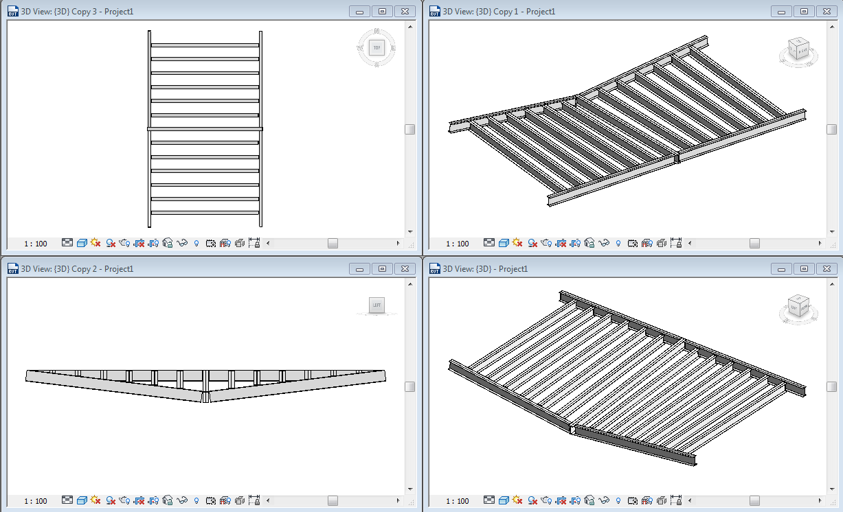
Have a look at the attached image. I created the support beam flat, then used Pick Supports to create the beam systems. Then I lowered one end of the beam by changing it's relative elevation and Voila !
-----------------------------------
.
FULL 'DOWNLOAD ACCESS' to all 850+ CADclips videos for only $150
|
This user is offline |
View Website
|
|
|
active
Joined: Thu, Mar 17, 2005
1231 Posts
|
This video I made might help clear it up..
Edited on: Thu, Jan 7, 2016 at 3:42:33 AM
Edited on: Thu, Jan 7, 2016 at 3:44:20 AM
-----------------------------------
.
FULL 'DOWNLOAD ACCESS' to all 850+ CADclips videos for only $150
|
This user is offline |
View Website
|
|
|
active
Joined: Mon, Mar 30, 2015
0 Posts
No Rating |
Thank you for the video!
I finally got it. The prob was I had a different work plane set and didn't know it.
|
This user is offline |
|
|
|
Similar Threads |
|
Concrete columns behaviour before and after placing concrete beams |
Revit Building >> Technical Support
|
Tue, Apr 1, 2014 at 1:58:43 AM
|
9
|
|
Imprecise beams! |
Community >> Newbies
|
Tue, Jun 22, 2010 at 10:20:46 AM
|
0
|
|
PLACING GIRTS AND BRACING |
Revit Structure >> Tips & Tricks
|
Fri, Oct 24, 2008 at 8:44:01 AM
|
0
|
|
joining two beams |
Revit Building >> Technical Support
|
Fri, Jul 6, 2007 at 12:03:10 PM
|
9
|
|
making beams dotted and upstands |
Revit Structure >> Technical Support
|
Tue, Jun 3, 2008 at 3:50:24 AM
|
7
|
|