Forums
|
Forums >> Revit Structure >> Technical Support >> Structural Connection Family
|
|
|
active
Joined: Thu, Jun 11, 2015
0 Posts
No Rating |
@pijpiwo, dzięki! I will do logics formulas in meantime.
I've noticed that HEB is placed in wrong way, it should be placed flanges to top and bottom (90 degrees from current position), therefore I've moved it, but the problem occurs to be a sweep work plane.
I don't have an idea how to connect a plane with sweep (and before I send that message I was looking for an answer in several places). When I am using reference plane it brings me back information about "too many constrains" and I have to removed them to continue. After I do that, unfortunately Void Extrusion doesn't rotate with HEB. How to solve that problem?
On the other hand, I would like to show that connection in one of several drawings and count both number of elements and it's length. Will that be possible, while we're using void extrusion to simply hide part of HEB?
PS Sorry for no images, I have very slow connection at the moment, however I've tried my best to describe problem.
EDIT: Is it possible to create a drawing for execution in Revit? I mean, for example, show welds.
EDIT2: How to lock plate on the top of HEB to ensure that plate will rotate in the same way as HEB?
Edited on: Fri, Jul 24, 2015 at 6:28:25 AM
Edited on: Fri, Jul 24, 2015 at 7:23:42 AM
|
This user is offline |
|
 | |
|
|
active

Joined: Fri, Sep 3, 2010
0 Posts
 |
"
I've noticed that HEB is placed in wrong way, it should be placed flanges to top and bottom (90 degrees from current position), therefore I've moved it, but the problem occurs to be a sweep work plane. In the HEB family, edit its profile. You need to do it anyway, because the current profile is nowhere near the actual shape/dim of the HEB 300/500. Delete void extrusion -> update HEB profile -> create new void extrusion (start with solid and when done, turn it into a void and cut the HEB), place it on the ref. line, the same as HEB and apply constraints, so the void rotates with HEB and keeps correct size/shape.
On the other hand, I would like to show that connection in one of several drawings and count both number of elements and it's length. Will that be possible, while we're using void extrusion to simply hide part of HEB? I’m not sure what you mean. Are you talking about schedules?
EDIT: Is it possible to create a drawing for execution in Revit? I mean, for example, show welds. If you plan on using it again in other projects, create a 2d drafting view to show all typical details (weld designation, etc.). It will be independent from the model element and it will not change with the 3d model/object. To show dimensions and details that change from project to project (plate size, thickness, HEB, angle, etc.), create a live detail view of a model.
EDIT2: How to lock plate on the top of HEB to ensure that plate will rotate in the same way as HEB? When you click on the ref line, you’ll see that it has 4 ref planes associated with it. Place your plate on the ref plane at the end of the ref line in the HEB family.
"
Edited on: Fri, Jul 24, 2015 at 6:09:05 PM
|
This user is offline |
|
|
|
active
Joined: Thu, Jun 11, 2015
0 Posts
No Rating |
"
"I've noticed that HEB is placed in wrong way, it should be placed flanges to top and bottom (90 degrees from current position), therefore I've moved it, but the problem occurs to be a sweep work plane. In the HEB family, edit its profile. You need to do it anyway, because the current profile is nowhere near the actual shape/dim of the HEB 300/500. Delete void extrusion -> update HEB profile -> create new void extrusion (start with solid and when done, turn it into a void and cut the HEB), place it on the ref. line, the same as HEB and apply constraints, so the void rotates with HEB and keeps correct size/shape.
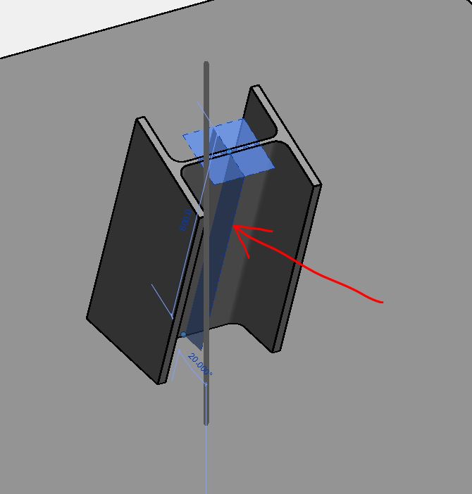
I have changed HEB dimensions then rotate profile about 90 degrees. Unfortunately, sweep plane doesn't rotate and it's still associated with side of profile. Somehow I managed to change plane to correct one, but then "error" occurs. Could you take a look on it?
I can't send you any private messages to not create a mess in forum, is it even possible?
Regards
Edited on: Mon, Jul 27, 2015 at 7:07:18 AM
|
This user is offline |
|
|
|
active
Joined: Fri, Sep 3, 2010
0 Posts
|
Void extrusion supposed to be on the ref line’s ref plane – see pic1. Make it current and draw a profile on it. HEB sweep appears to be correct. You have your parameters messed up a little, I think. I’m not sure what 'HEB hf' is doing and there is an error when entering any angle value. Take a look at the pic2. I’ve come up with a different formula. What it says is: if ‘Angle’ is 90, use ‘HEB Length’ (which is 1’-0” in this case), if ‘Angle’ is less than 90, add X to ‘HEB Length’, if ‘Angle’ is more than 90, subtract X from ‘HEB Length’. That’s basically what I’ve already written before, in my previous post.
I don’t think you can send PM on this site. Let’s keep it going here, others might want to join with some ideas.
|
This user is offline |
|
|
|
active
Joined: Thu, Jun 11, 2015
0 Posts
No Rating |
@pijpiwo, thanks to your hints, I've created needed HEB element with endplates. It occurs that all of my problems came from reference line as plane.
I am working now on materials - I would like materials to be the same in project as in reality. Nodes/HEB's & plate's material is Steel S235JR. Which Revit's material should I use? Or maybe I should download it from somewhere? Solved.
In case of other questions I will just edit that post.
Regards.
Edited on: Tue, Jul 28, 2015 at 5:11:19 AM
|
This user is offline |
|
|
|
Similar Threads |
|
Structural Connection not visible in Detail |
Revit Building >> Technical Support
|
Thu, Feb 23, 2017 at 10:42:26 PM
|
3
|
|
Revit 2017 Structural Connection - where is material defined? |
Revit Structure >> Technical Support
|
Wed, Jan 25, 2017 at 3:23:28 PM
|
0
|
|
Mechanical Revit Family with Multiple Connection Possibilites |
Revit Systems >> Technical Support
|
Wed, Dec 2, 2009 at 9:38:16 AM
|
0
|
|
2011 conduit connection |
Revit Systems >> Technical Support
|
Thu, Jun 10, 2010 at 1:15:54 PM
|
4
|
|
Alternative to a VPN connection for worksharing - Faster remote connection |
General Discussion >> Revit Project Management
|
Tue, Oct 12, 2010 at 8:51:02 AM
|
3
|
|
|
Site Stats
Members: | 1990808 | Objects: | 22877 | Forum Posts: | 152182 | Job Listings: | 3 |
|