Forums
|
Forums >> Revit Structure >> Technical Support >> Structural Connection Family
|
|
|
active
Joined: Thu, Jun 11, 2015
0 Posts
No Rating |
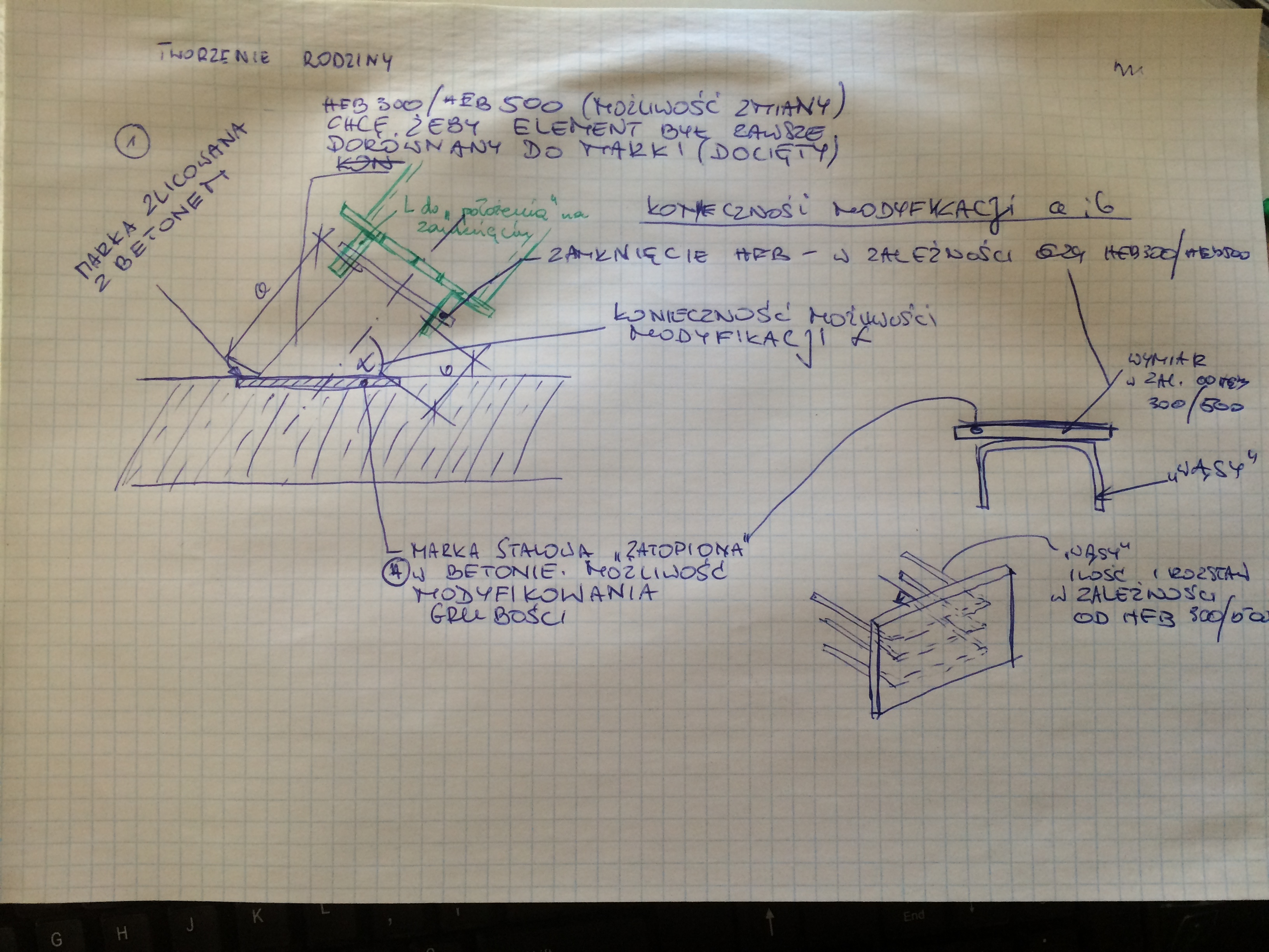
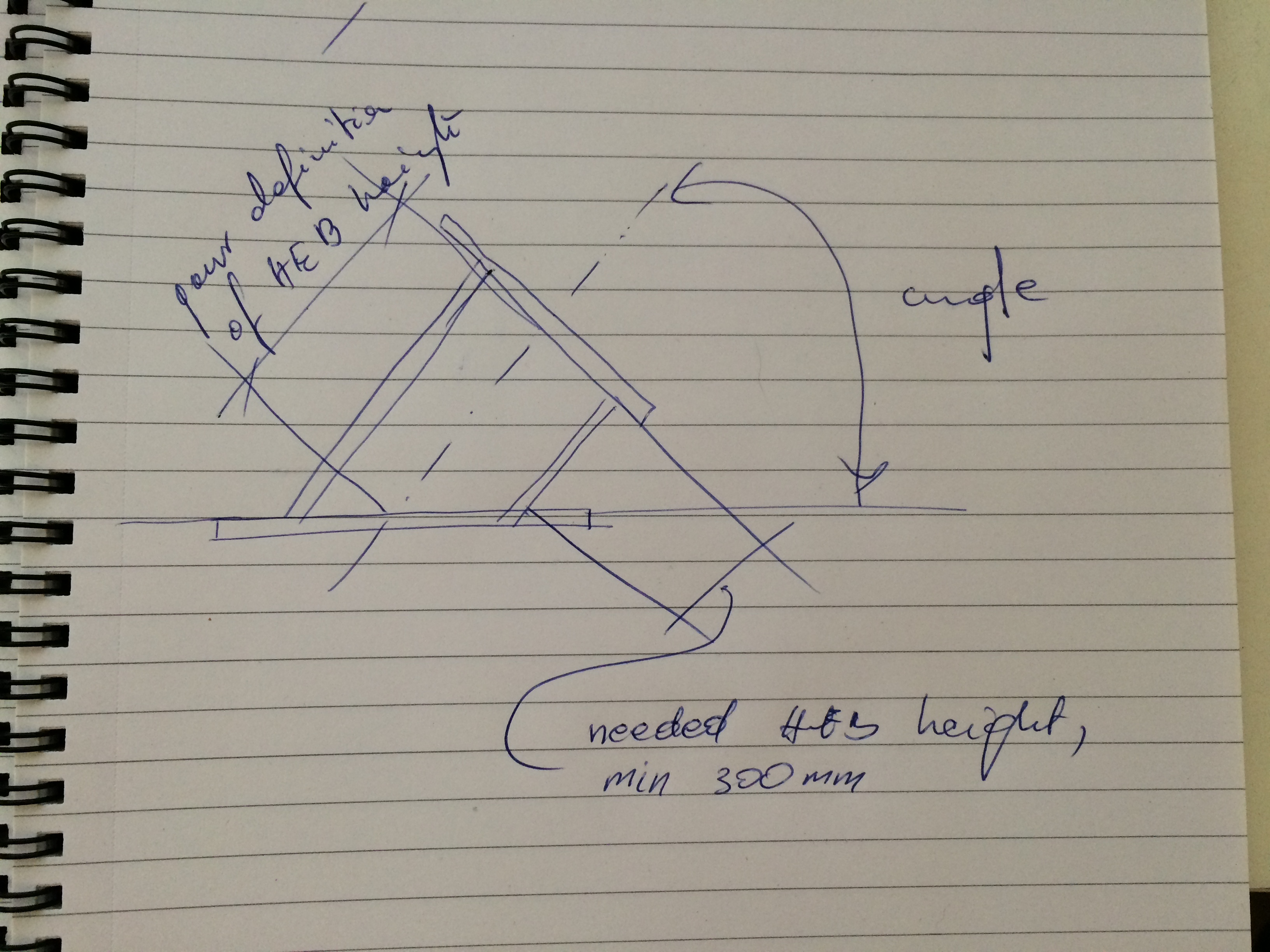
Hello to everyone, as it is my first topic here, on RevitCity. My problem is as following:
I would like to create a family, which makes possible for me create an element which you can see in attached image coloured in blue in any desired place in reinforcement wall. Element consists of HEB 300 or HEB 500 cutten as "sasuage" with ending plate and a plate placed in concrete with bars (in Polish: "wąsy") providing anchorage. It's important for me showing HEB cutted exactly like I want - in "sausage" way, and I am not interested in HEB which isn't connected directly to place based in concrete graphically as Revit provide normally. I want to have a possibility of changing HEB angle and it's ending in that way that HEB should always be cutted face-to-face with plate placed in concrete. Plate placed in concrete will be nested face-to-face with concrete itself, and then I would like to put it 20-50mm under the top level of concrete, but that I will probably manage to do with the help of elevation/view (I can't find any other solution, but if you know it, please be my guest!  ) In the picture you can also find a green part - it is next element, consisting of wide pipe, it's closure as plate and welded to it two angles. Those two angles will be next placed at the top of ending plate of HEB300/HEB500. Is it possible to put them directly in that place? ) In the picture you can also find a green part - it is next element, consisting of wide pipe, it's closure as plate and welded to it two angles. Those two angles will be next placed at the top of ending plate of HEB300/HEB500. Is it possible to put them directly in that place?
Please see also attached sketch.
Best regards.
|
This user is offline |
|
 | |
|
|
site moderator|||
Joined: Tue, May 16, 2006
13079 Posts
 |
Create a face based family that cuts the host and nest a plate family it that or create it in this family.
|
This user is offline |
|
|
|
active
Joined: Thu, Jun 11, 2015
0 Posts
No Rating |
Thank you for your quick response.
I am pretty new in family creation, where I can find more detailed description? Could you please explain it for me step by step or give me a link to video or maybe share a similar family with me?
Regards.
|
This user is offline |
|
|
|
site moderator|||
Joined: Tue, May 16, 2006
13079 Posts
|
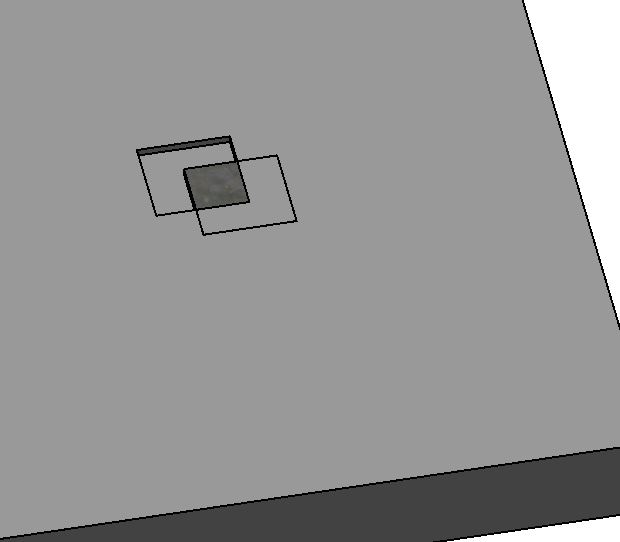
Attached is a beginning of a family. I used the generic - faced based template. As you can see from my image, I only have a plate and a void. I create the void off to the side and set it to cut the host. You can also just create the void first in the right place. If you don't do either of the above, the void may also cut your solid. As you can see from the image, the plate will not show correctly if you don't cut the host.
Play with this family looking at the void and solid properties. I suggest you start with reference planes to control the dimensions - I did not. Learn...........
|
This user is offline |
|
|
|
active
Joined: Thu, Jun 11, 2015
0 Posts
No Rating |
Once again WWHub thank you for your response.
In my opinion that part is the easiest, and until now I have managed to create a face-based plate with all dimensions needed. My problem is rather to introduce HEB, anchoring bars and cutting one element to another (with burried in mind that angle can change). Could you please help me with that?
Btw. I am learning using your answers. Next time I will know how to deal with it.
Regards.
|
This user is offline |
|
|
|
site moderator|||
Joined: Tue, May 16, 2006
13079 Posts
|
Download the 'families guide' from the autodesk site.
http://knowledge.autodesk.com/support/revit-products/troubleshooting/caas/sfdcarticles/sfdcarticles/Autodesk-Revit-Architecture-Families-Guide.html
It will show you how to control angled elements in families and much MUCH more.
|
This user is offline |
|
|
|
active
Joined: Thu, Jun 11, 2015
0 Posts
No Rating |
@WWHub, thank you for that toutorial, I have gained more experience in Revit Families than it's possible thanks to YT
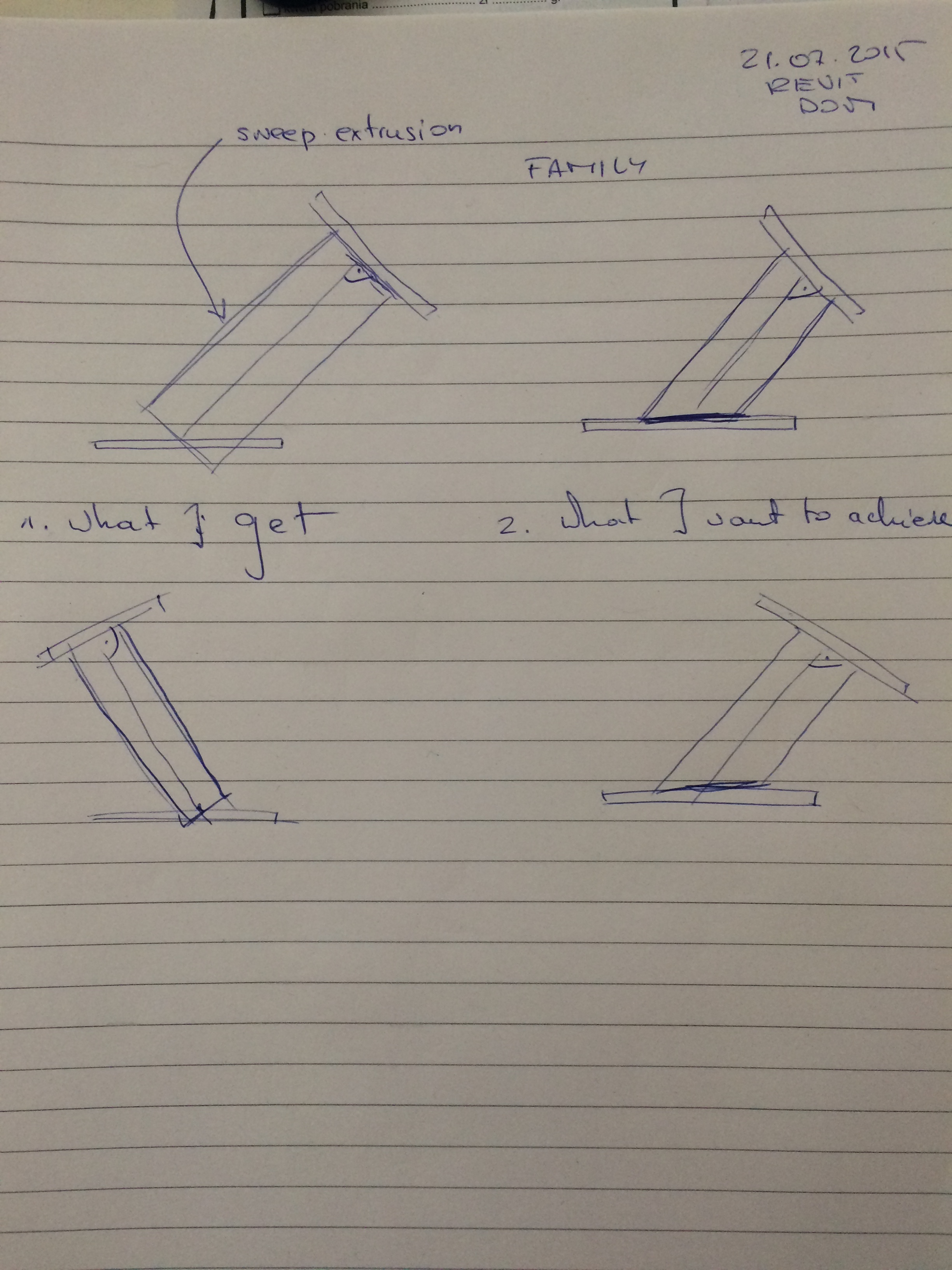
However, I still have a problem with that task, and this time I hope that you will be able to help more directly. Please see attached file.
The problem is to cut I-section in that manner that it will be all the time in one line with plate based in concrete.
Hope to hear a respond soon,
Regards.
|
This user is offline |
|
|
|
site moderator|||
Joined: Tue, May 16, 2006
13079 Posts
|
Use a reference plane and the CUT - pick beam then reference plane.
|
This user is offline |
|
|
|
active
Joined: Thu, Jun 11, 2015
0 Posts
No Rating |
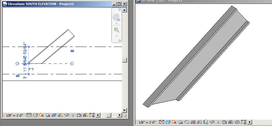
Unfortunately, I've done what you've said, but nothing happened. Namely, when I am picking cut, then sweep extrusion I cannot pick a reference plane. Could you please take a look to my Revit file attached to the post above?
|
This user is offline |
|
|
|
site moderator|||
Joined: Tue, May 16, 2006
13079 Posts
|
Sorry - no family was attached.
Was this still in a family? Are you really modeling structural elements in a family? I would have assumed you were only modeling the connector and let the structural element be in the project. The method I presented is in the project and that is a better solution.
If this is a sweep in the family, then you will have to add a void there to cut it.
|
This user is offline |
|
| |
|
|
active
Joined: Thu, Jun 11, 2015
0 Posts
No Rating |
My bed, please see family attached now. It's different, but the same principle (look at the hanger connection to beam)
Yes, it is still in family. I would like to do it in that way, because that element is in use often. Generally that is an connector at the end of that will be plate and then, due to the angles, another structural element -> pipe, beam will be placed on it.
|
This user is offline |
|
|
|
active

Joined: Fri, Sep 3, 2010
0 Posts
 |
If you’re new to a family creation, you have picked rather challenging family to tackle. Take a pick at the enclosed file and reverse engineer it. It’s created rather quick and rough, but you can use it as a sample to make your own, or refine mine to suit your needs. Two HEB families are nested into the plate family with family type parameters so you can swap these two. HEB family is a sweep created with a ref. line to control the angle and the height/length, and a void extrusion to cut off its excess. Hope it helps.
|
This user is offline |
|
|
|
active
Joined: Thu, Jun 11, 2015
0 Posts
No Rating |
@pijpiwo, thank you for your contribution. BTW, jesteś Polakiem?
I am in the middle of decoding parts of family, namely HEB2, which I have already changed into HEB300, however I have first question connected with that, please see attached image.
You are measuring distance between start and end of the centerline of the HEB, and for the construction purposes I would rather need exact 300mm for the smaller part of the HEB300, as shown in attachment.
Moreover what do you think about ending plate - should it be also connected to that family or rather should be use as another family?
EDIT: I've digged out some drawings from CAD, maybe that will be helpful. Generally temporary piping consists of 2 structural connections, one with cleat as you can see in PDF 01 and pipe.
In second PDF you can see only structural connection, top part is used with the end of pipe when cleat is used, the second one doesn't use anything more.
Please see mentioned above loaded on my Dropbox: https://www.dropbox.com/sh/l59d0waqc9u6tq0/AADvCW7omJbaMvBL-dajColTa?dl=0
Thanks for your all help for now, I will be glad if you can help me with that as well.
Regards.
Edited on: Wed, Jul 22, 2015 at 7:39:46 AM
|
This user is offline |
|
|
|
active
Joined: Fri, Sep 3, 2010
0 Posts
|
"
BTW, jesteś Polakiem? Oczywiscie ze tak.
You are measuring distance between start and end of the centerline of the HEB, and for the construction purposes I would rather need exact 300mm for the smaller part of the HEB300, as shown in attachment.
Moreover what do you think about ending plate - should it be also connected to that family or rather should be use as another family?
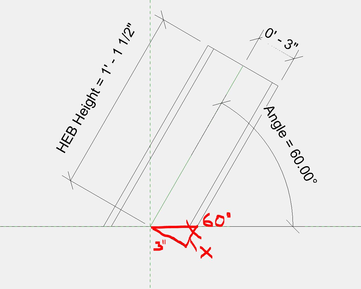
In the HEB family, you need to use some trig and formula to get that length. Create a new parameter, let’s say ‘HEB Length’ (no dim necessary) – it will be your input value, which will drive the ‘HEB Height’ parameter. Get the X value (pic 1) and subtract it from the ‘HEB Height’, or add depending on the angle. The formula (in the HEB Height’s formula field, pic 2) will have to be nested conditional statement, something like this:
if the angle is 90 deg, then use HEB Length, or
if the angle is less than 90 deg, then add X to HEB Length, or
if the angle is more than 90 deg, then subtract X from HEB Length
I’m not sure if RevitCity has any sticky on formula syntax, but you can find some here or search the web. At first it might look scary, but it’s really not - just some trigs, that’s all …and it’s a great exercise, you will learn something.
In regard to end plate, put it in the HEB family, I don’t think it has to be nested.
|
This user is offline |
|
|
|
active
Joined: Thu, Jun 11, 2015
0 Posts
No Rating |
@pijpiwo, dzięki! I will do logics in meantime.
I've noticed that HEB is placed in wrong way, it should be placed flanges to top and bottom (90 degrees from current position), therefore I've moved it, but the problem occurs to be a sweep work plane.
I don't have an idea how to connect a plane with sweep (and before I send that message I was looking for an answer in several places). When I am using reference plane it brings me back information about "too many constrains" and I have to removed them to continue. After I do that, unfortunately Void Extrusion doesn't rotate with HEB. How to solve that problem?
On the other hand, I would like to show that connection in one of several drawings and count both number of elements and it's length. Will that be possible, while we're using void extrusion to simply hide part of HEB?
PS Sorry for no images, I have very slow connection at the moment, however I've tried my best to describe problem.
|
This user is offline |
|
|
|
Similar Threads |
|
Structural Connection not visible in Detail |
Revit Building >> Technical Support
|
Thu, Feb 23, 2017 at 10:42:26 PM
|
3
|
|
Revit 2017 Structural Connection - where is material defined? |
Revit Structure >> Technical Support
|
Wed, Jan 25, 2017 at 3:23:28 PM
|
0
|
|
Mechanical Revit Family with Multiple Connection Possibilites |
Revit Systems >> Technical Support
|
Wed, Dec 2, 2009 at 9:38:16 AM
|
0
|
|
2011 conduit connection |
Revit Systems >> Technical Support
|
Thu, Jun 10, 2010 at 1:15:54 PM
|
4
|
|
Alternative to a VPN connection for worksharing - Faster remote connection |
General Discussion >> Revit Project Management
|
Tue, Oct 12, 2010 at 8:51:02 AM
|
3
|
|
|
Site Stats
Members: | 2161655 | Objects: | 23325 | Forum Posts: | 152479 | Job Listings: | 3 |
|