Forums
|
Forums >> Revit Building >> Technical Support >> Line Subcatergory
|
|
|
active
Joined: Mon, Feb 10, 2014
0 Posts
 |
I've created a door family that allows me to adjust the door swing angle in plan view. I was able to do this by creating a detail item of the door and swing with it's own instance parameter and then loading it into my door family.
Here's my problem: The symbolic lines in the door family has a collection of "Subcatergory" options such as "Panel [Cut]", "Panel [Projection]", etc. But because I had created the adjustable door swing as a detail item, my "Subcatergory" options for that are limited to "Detail Lines" and "Hidden Lines." Basically I want the lines in my detail item to match the "Panel [Cut]" lines in the door family. Is there a way to do this? Can I create a new "Subcatergory" in my detail item that mimics the lineweight of the "Panel [Cut]" lineweight? Or can I at least tweak the lineweights of the lines in my detail item?
|
This user is offline |
|
 | |
|
|
site moderator|||
Joined: Tue, May 16, 2006
13079 Posts
 |
Seems like it would be far better to have just done it in the door family............
Sorry - detail items are detail.
The "families guide" downloadable from the autodesk site walks you through creating a door family.... and how to do angles.
|
This user is offline |
|
|
|
active
Joined: Mon, Feb 10, 2014
0 Posts
|
I'll check that out.
But in general, is it even possible to change the lineweight or line styles when creating a detail item? It seems odd that I can create a detail group in a project file and use any of my downloaded line styles, but I don't have that option when creating a detail item in a family file. What if I wanted to create a detail item that had heavy lines, or dotted lines? Am I just out of luck in that case?
|
This user is offline |
|
|
|
site moderator|||
Joined: Tue, May 16, 2006
13079 Posts
|
Read your HELP:
Creating a Line Style
http://help.autodesk.com/view/RVT/2014/ENU/?guid=GUID-9C8D3F0E-B1C5-42B5-8920-FBD2D4992E47
|
This user is offline |
|
|
|
active
Joined: Mon, Feb 10, 2014
0 Posts
|
Thanks, unfortunately it didn't help out much. As soon as I reloaded the detail item back into the door family, the lineweights reverted back to their original form, and there wasn't an option to change them in the Manage tab.
I think I figured it out, but those instructions in the Autodesk Families Guide are pretty awful. There's no mention of locking the reference line onto the appropriate planes, nor is there any mention of locking constraints on the door itself so that it stay's rectangular when you rotate it. If I follow their instructions exactly, only the line that's drawn over the reference line rotates while the other three lines of the door stay in place and stretch around. Plus, the reference line shifts along the face of the wall and is only in the right place when the swing angle is at 90 degrees. Once I properly locked the reference line and symbolic lines, everything seemed to work (at least for the single swing door, still working on the double-door).
|
This user is offline |
|
|
|
site moderator|||
Joined: Tue, May 16, 2006
13079 Posts
|
You are mistaken. The guide doesn't tell you about locking because in most cases, you don't need to. Over locking can cause problems.
The line that lines on the reference line will rotate as it should. If you want the ather elements to rotate with that line, they also ened to be constrained to it.
The reference line will never shift as you described. The reference line will rotate around it's end. What you are probably seeing is the other elements have moved away because something was not done correctly.
Keep working at it and you will learn.
|
This user is offline |
|
|
|
active
Joined: Mon, Feb 10, 2014
0 Posts
|
"You are mistaken. The guide doesn't tell you about locking because in most cases, you don't need to. Over locking can cause problems." ... "The reference line will never shift as you described. The reference line will rotate around it's end. What you are probably seeing is the other elements have moved away because something was not done correctly."
Perhaps I'm referring to the wrong section, but I had followed the directions in the section labeled "Controlling Angular Dimensions with Reference Lines" (page 86) of the Families Guide. When I follow those directions exactly, I do not get the desired result. I've attached some screenshots to show you what I mean.
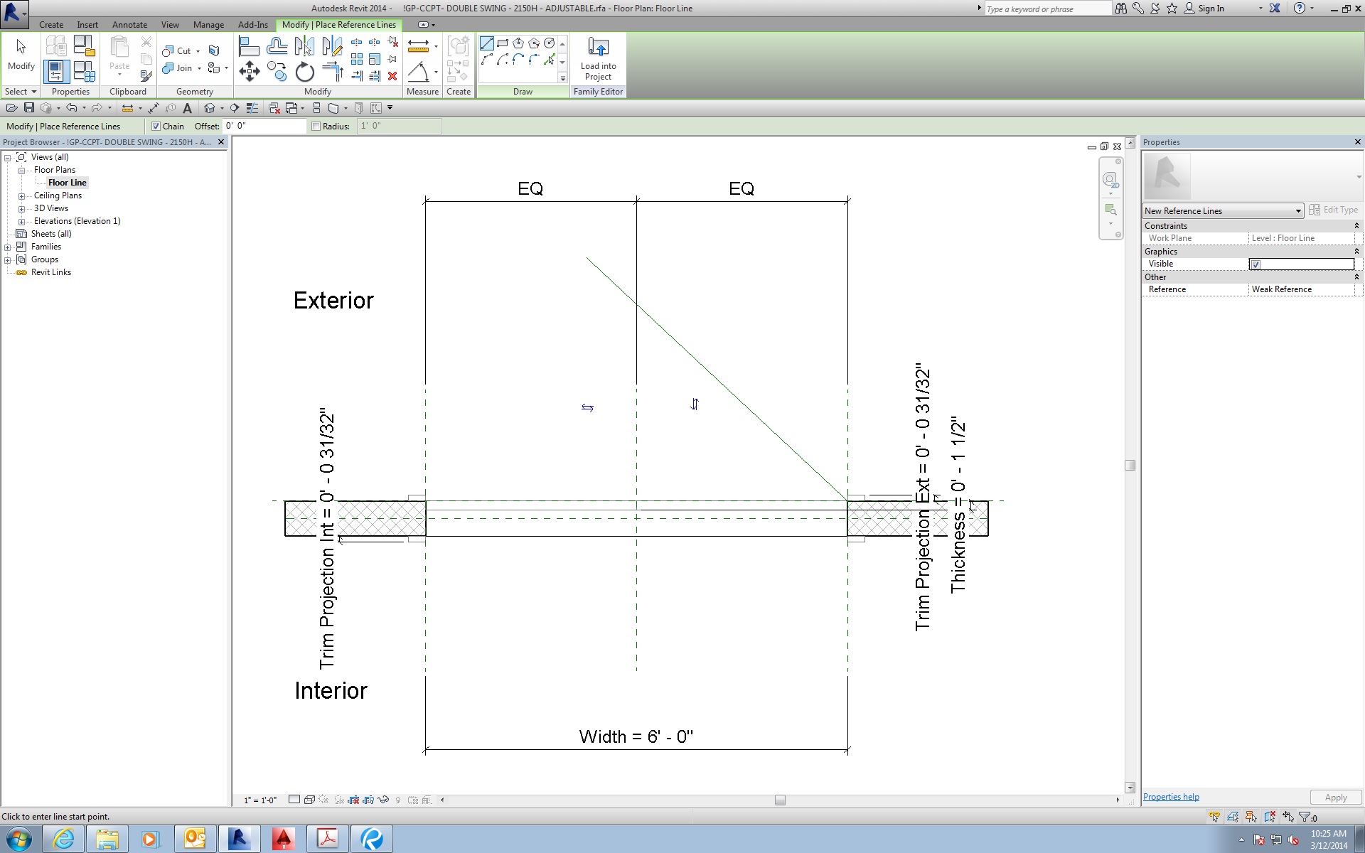
Image 1: I draw a reference line starting at the point of rotation, exactly as explained in the instructions.
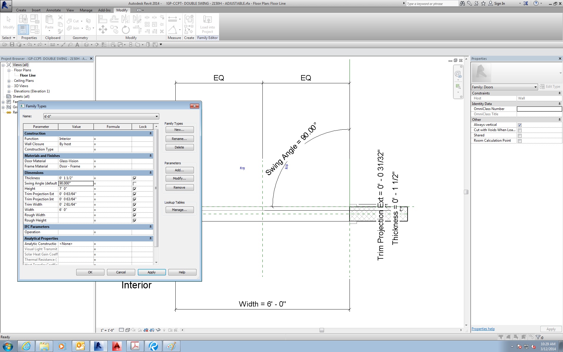
Image 2: I add an angular dimension from the reference plane on the exterior face of the wall to the reference line. I then added the "Swing Angle" parameter. (I had already made the "Swing Angle" parameter the last time I was in this file, and the default angle was 60 degrees).
Image 3: I open the Properties panel and change the "Swing Angle" to 90 degrees. So far so good...
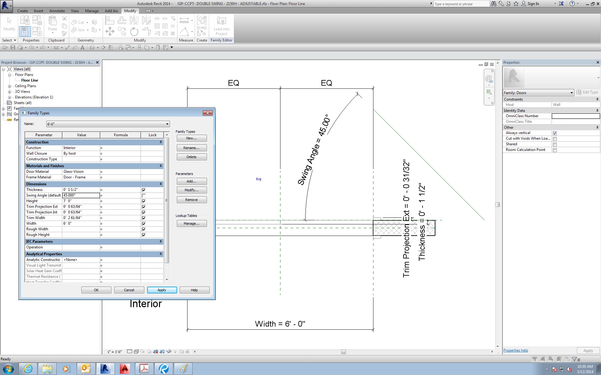
Image 4: I then change the Swing Angle to 45 degrees. Notice that the reference line has now shifted along the face of the wall. The wall doesn't move (unless you're trying to tell me that the wall moved and that camera moved with it, giving the illusion that only the reference line moved...that would just be weird.) This is what I'm talking about. From this point on, any value I input for the "Swing Angle" other than 90 degrees results in the reference line shifting.
"The line that lines on the reference line will rotate as it should. If you want the ather elements to rotate with that line, they also ened to be constrained to it."
I know, that was exactly my point. That's why I was surprised that the instructions in the Families Guide (at least in that section) makes no mention of constraining the geometry. The instruction simply says to set the work plane on the reference line and then any geometry will rotate with it. When I did it, only the line drawn directly over the refernce line rotated with it.
The bottom line, though, is once I locked the endpoint of the reference line to both the vertical and horizontal reference planes, it rotated perfectly without any shifting. As for the geometry, simply setting the work plane drawing the rectangle wasn't enough. I would draw the first line right over the reference line, then do a Pick Lines with an offset to make the parallel line. That offset is automatically locked to my first line. I then draw the other two lines to complete the rectangle and I only need to contrain one of the angles to maintain the rectangle's shape. After all of that (and after repeating the same process for the other door) everything worked fine.
|
This user is offline |
|
|
|
site moderator|||
Joined: Tue, May 16, 2006
13079 Posts
|
Check out this family. My reference line is not locked and this family does not break nor does the reference plane move as yours does.. Change the type values width and angle to test it.
This family shows how I build around a work plane instead of the wall. Where you built the family causes your problems.
|
This user is offline |
|
|
|
active
Joined: Mon, Feb 10, 2014
0 Posts
|
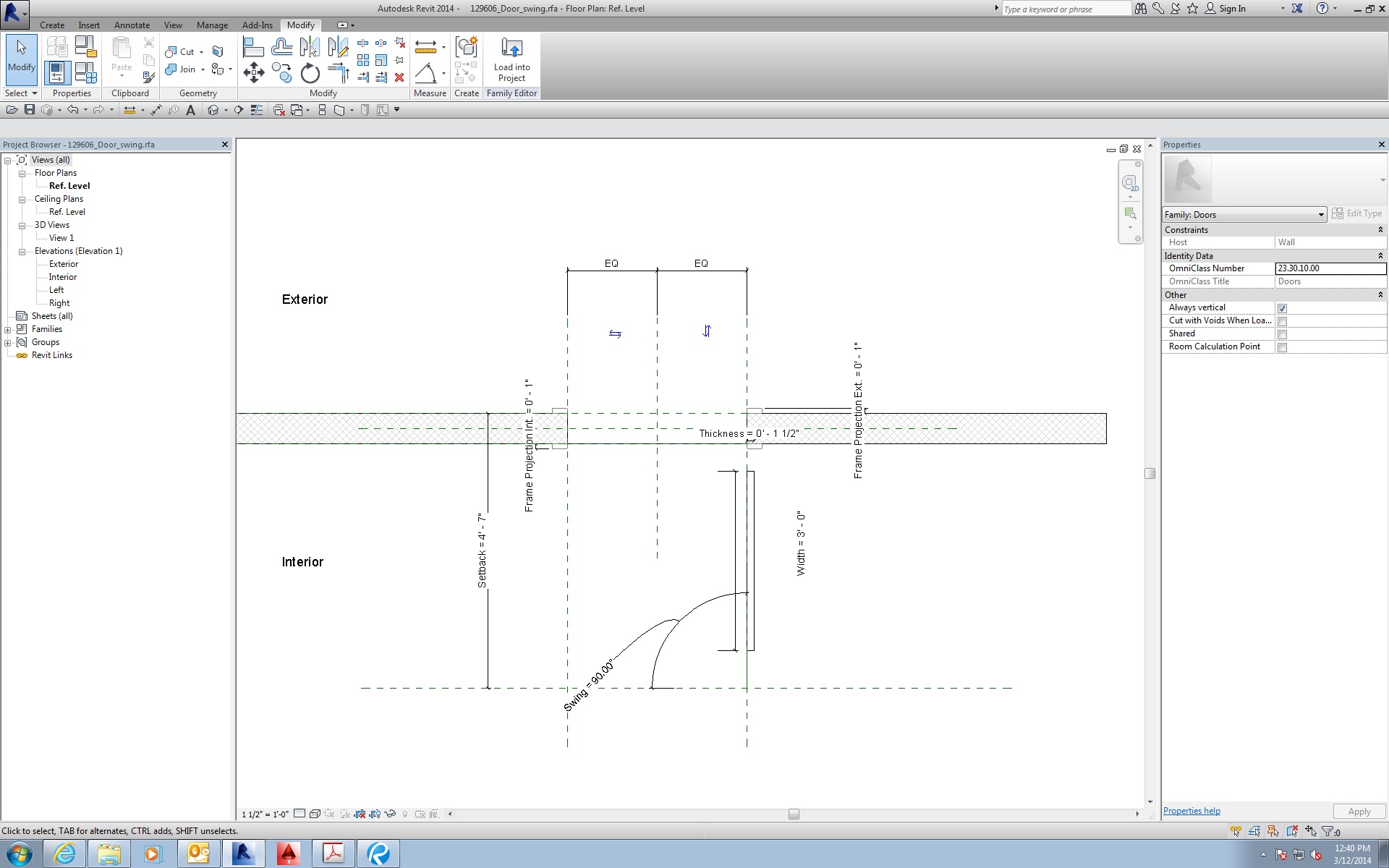
I opened your door family and the first thing I did was open the Family Types menu and change the Swing angle from 45 degrees to 90 degrees. I attached an image of what I got. The door isn't even attached to the reference plane anymore, my guess is because it wasn't properly locked. Is this what happens when you do the same?
I had made my door the same way you had made yours, except I kept my reference plane aligned to the exterior face of the wall instead of offsetting it. I just make sure that my reference plane extends past the ends of the wall so that I can easily select it when needed.
|
This user is offline |
|
|
|
site moderator|||
Joined: Tue, May 16, 2006
13079 Posts
|
You never want to set a swing to 0, 90 or 180. It will always break.
You still are not understanding. Revit is always making associations when elements are close to each other. You may think you are building around the face of the wall.... or the reference plane at the face of the wall but Revit may be making an association with the center of the wall. Often you will see these families break simply when they are in a project with a thicker wall. These associations are hard to control unless you lock everything to a work plane or dimension lock to another locked element.
Do this test... edit the wall in your family and change it to twice it's thickness. Does it work correctly? If it does, then good for you. If not then you will see that you have problems.
Revit does do funny things with angles that you have to watch out for. If you take the family I sent an set it to 30 to start so that everything is correct. Now set it to 160 and whoops.... the reference line moves correctly but the door leaf flips to the complementary angle. Undo this and change the angle incrementally up to... 40, 60, 80 then 160.... All don't have a problem. Set to 30 and it will flip again. Revit seem to loose the proper association once the angle difference is greater than 90.
|
This user is offline |
|
| |
|
|
active
Joined: Mon, Feb 10, 2014
0 Posts
|
"You never want to set a swing to 0, 90 or 180. It will always break."
Ok, now you've lost me. Why on earth would anyone want a door that can't make a 90 degree swing angle??? And the fact that your door clearly doesn't stay attached to the work plane when you said it would...
I don't think you're giving me enough credit here. You keep saying that I "don't understand," but then you give me a door that has way more problems than mine did before I had corrected them. There's no doubt in my mind that you are wayyy more knowledgable in Revit than I am, but in regards to this door issue, the things you're telling me just aren't adding up.
Attached is my completed door (functionally, anyways. At some point I'm going to redesign the "frame"). Using the methods I had suggested (strategic locking and constraining), you can now swing this door at any angle between 0 and 180 (I created a Failsafe Angle to allow it to swing at 0). You can even change the wall thickness and it won't affect the door. It even works across family types.
I'm not trying to say that this is THE correct way to make an adjustable swinging door, but it's hard to argue with the results here. It wouldn't hurt to try some of these methods on your door to resolve those 0-90-180 problems.
|
This user is offline |
|
|
|
Similar Threads |
|
Decal Placement |
Revit Building >> Technical Support
|
Wed, May 1, 2013 at 7:55:41 AM
|
1
|
|
Anyone got line styles that will automatically insert a letter.... |
Revit Structure >> Technical Support
|
Wed, May 2, 2012 at 8:29:56 AM
|
8
|
|
Line Patterns |
Revit Building >> Technical Support
|
Tue, Aug 9, 2005 at 3:08:30 PM
|
6
|
|
Any Suggestions For Line wt Table set up and Line Style Names |
Revit Building >> Technical Support
|
Thu, Jun 5, 2008 at 7:01:45 AM
|
5
|
|
Line types |
Revit Building >> Technical Support
|
Thu, Nov 17, 2005 at 2:53:43 AM
|
3
|
|
|
Site Stats
Members: | 2161655 | Objects: | 23325 | Forum Posts: | 152479 | Job Listings: | 3 |
|