|
Forums >> General Discussion >> Revit Project Management >> Drafting a wall section
|
|
|
active
Joined: Tue, Jul 16, 2013
3 Posts
 |
We are working with certain walls that are just not able to be modeled correctly in Revit. So we are having to draw all of our wall sections in drafting views. The drawing part for us is not a big deal because a lot of the sections that we already have drawn in autocad from previous projects can be reused and modified for future projects (and we have already converted the autocad versions into Revit drafting views). Here is the issue. In autocad when you draw a wall section, you have your elevation xref'd into the drawing and you use it to determine the majority of your horizontal dimensions. In Revit is it possible/common for people to drag a view of their elevation into each of their drafting views to construct a wall section? If so, that seems like a pain but whatever. The other option I see is to create a wall section and have it reference our model, which would give us a section that would look pretty horendous. However, if those model elements could be put on a Defpoints layer in our wall section callout then we could still have that benefit of referering to the elevation/model when constructing our wall sections and allow us to have the desired wall section using 2d drafting lines on top. Having the model objects behind our drafting lines would also act as red flag when something in the model changes. If a Defpoint layer is not possible are there any other options to achieve something similar?
|
This user is offline |
|
 |
|
|
|
site moderator|||
Joined: Tue, May 16, 2006
13079 Posts
 |
Use the power of Revit. Create model views and paste your drafting elements into it. You can turn off any model components you don't want to use or even all of them.
|
This user is offline |
|
|
|
active

Joined: Thu, Mar 17, 2005
1231 Posts
|
I'm very curious about what makes your walls so unique that they cannot be modeled or should I say modeled correctly and not be good enough to be used in a section ? So are your elevations full of 'detail lines' ?
Is the problem the floor / roof tie-ins, exterior projections, materials, glazing ? You're heading down the yellow brick road Dorothy. Upload an image of the wall section shown correctly in it's drafting format and lets take a look at it. If you can model it even closely the section will be usable. Then you embelish with all kinds of smart detail component families, cut profiles, repeating details, symbols, booleen operations, filled regions etc.
-----------------------------------
.
FULL 'DOWNLOAD ACCESS' to all 850+ CADclips videos for only $150
|
This user is offline |
View Website
|
|
|
active
Joined: Tue, Jul 16, 2013
3 Posts
|
If you scroll down about 25 threads in this same Revit Project Management Tab, you'll see a rather long post I made called "detailing a tilt wall". It describes most of the problems I am having, and there is a picture posted. Some things got figured out but most of them did not. nbd, I'm still all ears.
Some of the problems could be solved through the use of excessive hatching in order to blend parts of the wall together but it just seems that some of the things I would have to do to make it right in revit would take longer than just using the drafting views we already have created. But also I'm also pretty sure some of the things in my previous post ARE impossible to efficiently accomplish in a revit building model. Have a look.
http://www.revitcity.com/forums.php?action=viewthread&thread_id=31744
|
This user is offline |
|
|
|
active

Joined: Sun, Oct 19, 2008
101 Posts
 |
Grem -
This looks like a typical 3-3-4 concrete sandwich panel. I just completed a project EXACTLY like the image you showed. I have no problem sending you my wall profile in revit 2013. A couple things are different here and there, but if you reverse engineer what I have, you should be able to easily be able to create it in 3D rather than a drafting them.
I'd send it now but I'm on my tablet. We've done some pretty insane work for high-end firms, you should see what they want us to do in Revit, yikes. 
-----------------------------------
RB Cameron
3D Medical Equipment
Download Revit Healthcare Models Now
Download Other Revit + 3dsMax Models Here |
This user is offline |
View Website
|
|
|
active
Joined: Tue, Jul 16, 2013
3 Posts
|
I'd love to see how you accomplished your tilt/sandwich panel construction wall.
Some of the major areas that I'm trying to figure out include: allowing the insulation to taper in towards the top of the wall to allow for more meat of the outer layer of concrete to be used as a parapet, have all 3 layers of the wall adjustable vertically (revit won't let you just unlock all the layers and move them independently, the most you can do is 2), and lastly have the walls inner layer of concrete wrap at certain door openings (at overhead door openings, not single metal door). Unless the best approach is to add hatching to the door family so it overlays the wall when cut in section. The concrete also wraps at the bottom of the wall but I've already figured out how to make that happen using the split and merge commands.
|
This user is offline |
|
|
|
site moderator|||

Joined: Fri, Nov 12, 2010
1749 Posts
|
A lot of your wall can be done using the standard wall construction as rbcameron2 says, for the things that don't do exaclty what you want you would just use filled regions and detail components to make the sections look correct.
|
This user is offline |
View Website
|
|
|
site moderator|||
Joined: Tue, May 16, 2006
13079 Posts
|
Gremmels,
When we need the cut profile of a wall to be different in a view then the defined layers, we use the 'edit cut profile tool'. I think you need to look at that. That will allow you to "allowing the insulation to taper in towards the top of the wall to allow for more meat of the outer layer of concrete to be used as a parapet".
"have all 3 layers of the wall adjustable vertically (revit won't let you just unlock all the layers and move them independently"... << Revit lets you unlock adjecent layers. Sometimes that means you have to think in reverse. When you need to adjust both the inside and outside layer - you can't - Right? Well, instead unlock all the inside layers and move those instead.
"....and lastly have the walls inner layer of concrete wrap at certain door opening" << Could this be solved in the door family? If this not a 3D issue then maybe just using the edit cut profile in plan view works.
|
This user is offline |
|
|
|
active
Joined: Tue, Jul 16, 2013
3 Posts
|
I'm aware that most of any wall section can be accomplished using hatching. I'm more interested in finding out if there is a way to truly have it modeled in revit. Cause if I start hatching all over the place I'm essentially drafting. Also, if I hatch the outer layer of concrete at the top of the wall where it tapers in I've essentially just lied to the computer, saying I've modeled this wall to be "x amount" thick but in this view I'm going to make it "y amount" thick. Now what happens when I go to my roof plan and it still shows the wrong thickness because I haven't modeled it accurately? More hatching? What happens when the thickness changes? I would have to change each hatch/filled region in every wall section/detail. I woudn't classify this as standard wall construction for revit either, you're making it sound a lot easier than it actually is if you actually try and make these elements a part of the wall assembly and not something you just tack another hatch onto. That's what I'm looking for here, not hatching.
|
This user is offline |
|
|
|
active
Joined: Tue, Jul 16, 2013
3 Posts
|
In response to teafoe, not WWHub.
WWHub I will take a look at what you suggested
|
This user is offline |
|
|
|
|
|
site moderator|||
Joined: Fri, Nov 12, 2010
1749 Posts
|
I was not suggesting that you use filled regions to make your wall. I was stating that you can create your wall section just as rbcameron stated, basically that you CAN model the wall. I didn't mean to make it sound easier than it is but it is quite easy once you know what you are doing. WWHub took it one step further with the door family and edit cut profile tool. Good luck.
|
This user is offline |
View Website
|
|
|
active
Joined: Tue, Jul 16, 2013
3 Posts
|
My mistake teafoe.
WWHub. I like the suggestions, the cut profile tool seems like it will work really well for much of the wall wrapping and internal modifications. Still not sure about using it to modify the top of insulation and outer layer of concrete though because those modifications edit the exterior profile of the wall assembly, thus I will not see those changes reflected in a 3D view or roof plan. Maybe if I do a similar "reverse engineering" approach and create a new wall type that has the thicker parapet wall and then modify the internal structure. But then I will not see the insulation in the correct spot in plan view unless I stack 2 different walls. Looks like I have some ideas to play with here.
They really need to make this cut profile tool part of the wall assembly "edit type" as well. That would make it so much easier and any changes would be made globally. Either that or allow the cut profile modification to be reflected in the model itself. that would also help.
|
This user is offline |
|
|
|
site moderator|||
Joined: Tue, May 16, 2006
13079 Posts
|
All edit cut profiles are 2D only and is therefore not available in the wall description. But if you edit a wall say in plan, that same edit can be copy/pasted to any view that is the same orientation of the same components.
3d changes in wall thickness can be achieved by wall sweeps both in wall types or external and by in place families. An example of in-place sweeps is here in this log wall post I did awhile back: http://www.revitcity.com/forums.php?action=viewthread&thread_id=17944
That same concept can be used for any wall profile.
|
This user is offline |
|
|
|
active
Joined: Sun, Oct 19, 2008
101 Posts
|
GREMMELS
Sorry for the slow response, I've been in and out for the holiday season.
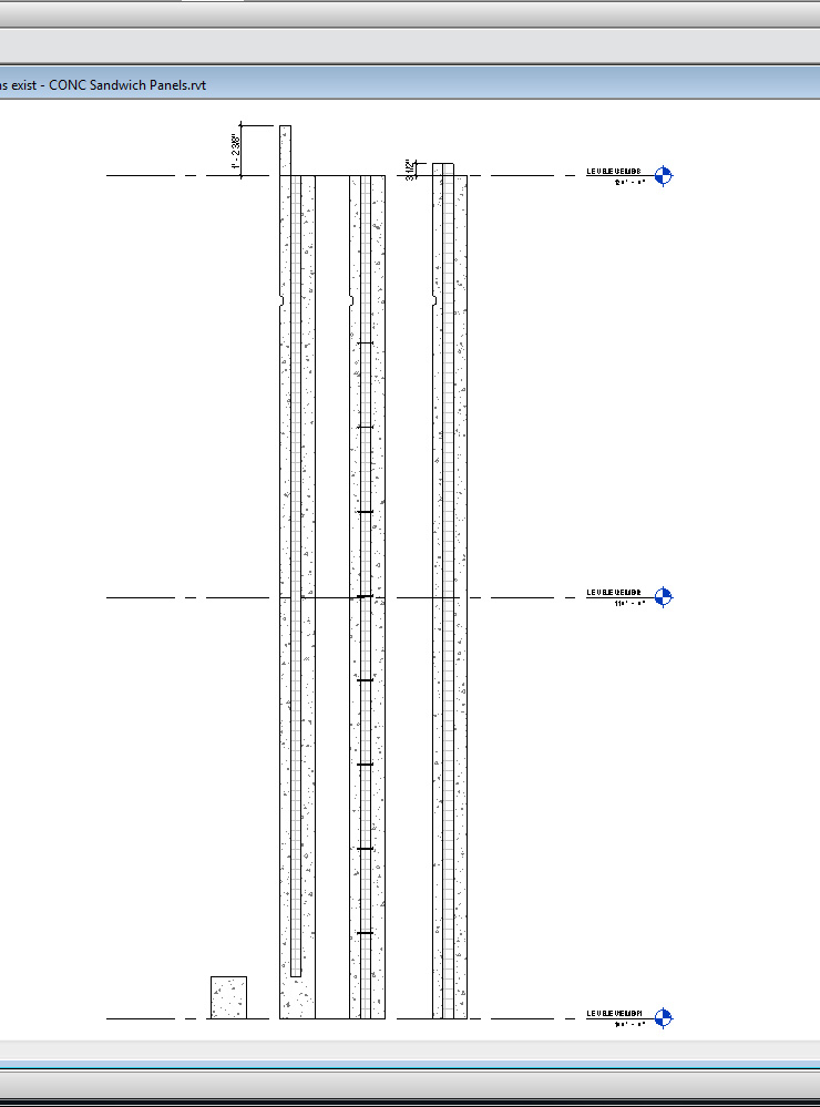
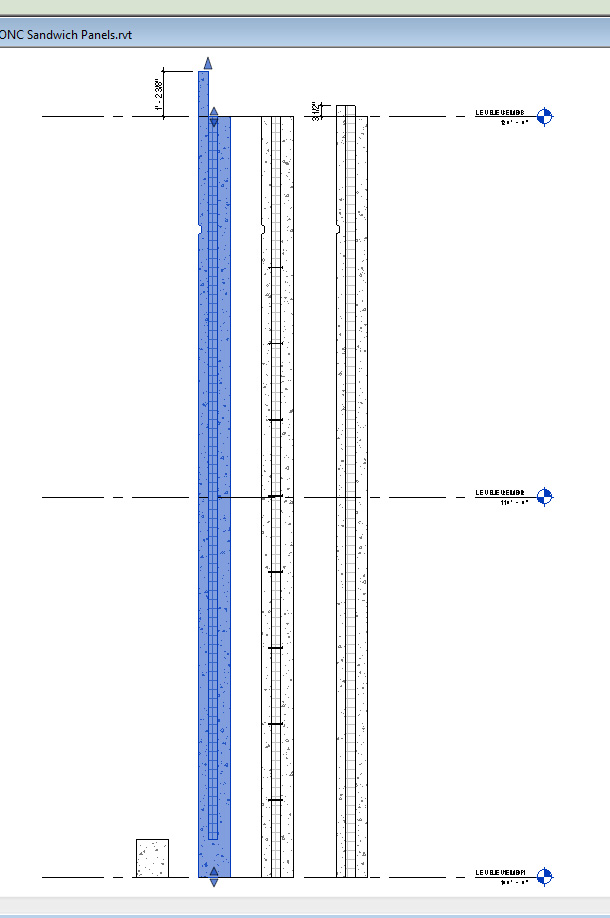
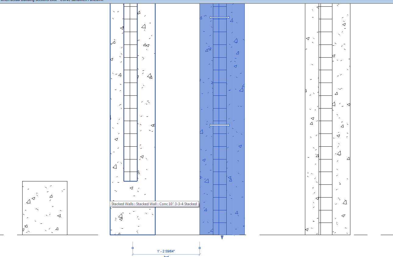
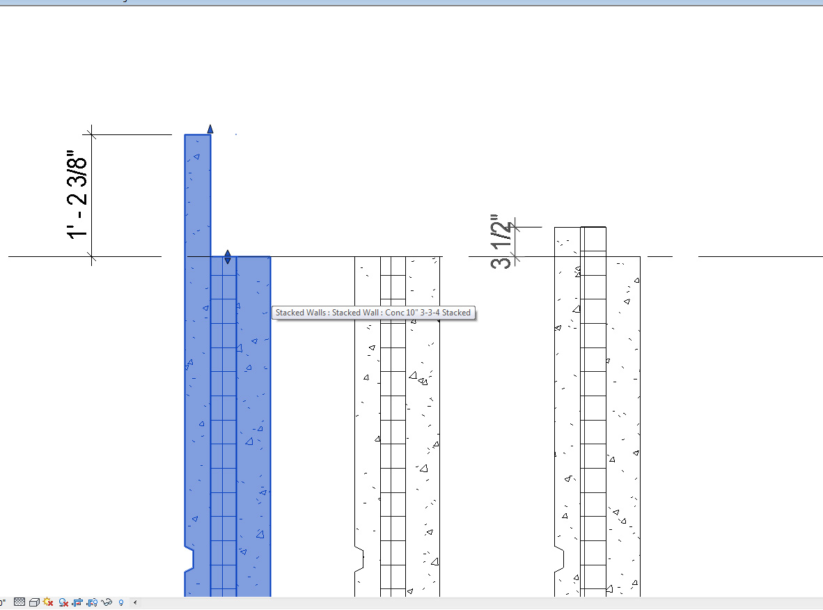
I take it you're looking for something like this... see attached.
What I did was create 2 wall types - both concrete, one is a 3-3-4 panel and the other is 10inch concrete. Technically I created a third wall type that is a stacked wall to include a 1'-0" section of the 10" concrete solid wall beneath. It is highlighted in blue.
I modified the top of the 3-3-4 panel to allow for the first 3"conc and 3" rigid insulation to move up and down. the blue highlighted image indicates that I used a cut profile to take it from there.
I also put a reveal (or you could switch it to a sweep) for the 24" O.C. panel reinforcement between the panels. that keeps you from having to detail component that thing in a dozen times.
also, for good measure I created that 3" notched reveal you had.
Attached is the file with the walls. I probably forgot a thing or two but this should be enough to get you started.
If you ever need anything else like custom families for healthcare or anything, I'm making a huge assortment at the link below my name.
-----------------------------------
RB Cameron
3D Medical Equipment
Download Revit Healthcare Models Now
Download Other Revit + 3dsMax Models Here |
This user is offline |
View Website
|
|
|