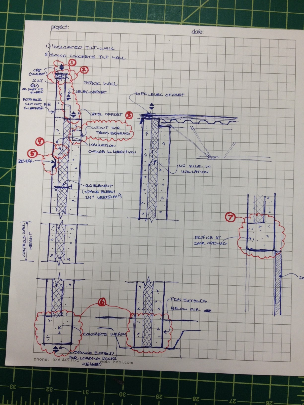
Looking for some solutions to this wall assembly. I have circled some of the issues I am having in the attached image. And am afraid that this type of modeling is just not possible in Revit, which would surprise me since this is pretty typical tilt wall construction. For all you heavy Revit users out there, how would you make a wall assembly such as this in Revit? What would you include, what would you leave out?
1) At the top of the Tilt Wall I need all three layers to be able to move up and down, due to different detailing around the building
2) The parapet cap when I place it in the wall assembly as a sweep must be attached to the top of the wall (must be attached to the wall in some way, will not allow me to have it hovering above the wall). Which means when I go to detail, it requires me to put a 2D 2x4/6/6 detail component within the wall. The problem is that when I dimension an elevation (in order to provide the overall height of the tilt wall) it will snap a dimension to the top of the modeled concrete, not accounting for the 1.5" detail component that was inserted into the wall section in 2D thus making the tilt wall 1.5" shorter than it is actually modeled.
3) In some instances, truss work will rest directly on top of the inner layer of concrete, other times it may rest in a void cut into the layer of concrete. What is the best way to puncture this void into the wall so that it reads correctly when cut through, or as a dash when not cut through in section.
4) The insulation as it reaches the top of the wall must taper inward in order to allow for more meat of the concrete to form a stable parapet wall. How can I get this angled transition to occur?
5) We are using reveals on the exterior face of the wall. In order to achieve this we loaded a profile into the reveals category of the wall. However graphically we are running into some issues. First, I'm not sure where you change the projection lineweight (elevation) of the reveal itself. Secondly, if I do find a way to change the lineweight it will still read as a heavy line because the reveal profile essentially creates 4 lines really close together due to the shape of the profile itself. The beauty of autocad and what we like to do as architects is to draw using symbols. Even though in elevation this reveal would have 4 horizontal lines running across, we really only need to show two lines in order to represent the reveal as a readable object in elevation and then move to a more detailed view in order to show the true geometry.
6) At the bottom of the tilt wall we have two different scenarios. The one on the left shows the inner layer of concrete wrapping underneath the insulation and continuing to be flush with the outer layer of lightweight concrete. The one on the right does not need this. I'm assuming that these two scenarios would have to be created using two different wall types. Thats fine i guess, but the assembly on the left with the wrapping concrete also needs to be able to extend downward to account for changes in grade.  also, I have already figured out how to make the concrete wrap around using the modify/split/merge commands in the wall editor, its the chaning/varying height that i need to figure out) perhaps yet another wall type? also, I have already figured out how to make the concrete wrap around using the modify/split/merge commands in the wall editor, its the chaning/varying height that i need to figure out) perhaps yet another wall type?
7) I have a similar wrapping effect that i need where there are overhead doors occuring. I guess there is no way for revit to know to wrap a certain amount of the concrete where you have a void(door) cutting into it (it's only at overhead doors that we need this detail, not single hollow metal doors)? The only other thing I can think of is to hatch over that area of the wall myself once a section has been created. Not too big of a deal, any other ideas?
Sorry for the length, thought I would be as thorough as possible considering that these questions aren't the easiest to explain, nor the easiest to answer. Thanks.
|