|
|
|
Home | Forums |
Downloads | Gallery |
News & Articles | Resources |
Jobs | FAQ |
| Join |
Welcome !
|
14 Users Online (12 Members):
Show Users Online
- Most ever was 626 - Mon, Jan 12, 2015 at 2:00:17 PM |
Forums
|
Forums >> General Discussion >> Revit Project Management >> REVIT FOR MAKING UTILITIES PLAN AND COINCIDENCE
|
|
|
active
Joined: Tue, May 26, 2009
2 Posts
No Rating |
Hello,
I am trying to get a workflow established for making a campus utility plan. One man operation here. I have began the process of making a background autocad map of the campus and then importing that basic map into Revit. The reason for this is that by making families of each utility line I can assign parameters for labeling the lines and creating a spreadsheet of conditions and locations (in the future GPS locations). Lines representing utilities can be assigned to the paticular family type are easily controlled for color and type and everthing looks really crisp and clean. The autocad drawing is of a different type that gets locked away from the revit stuff in its imported catergory. Adding man holes and valves means that there is consistency throughout the project. Yes, i know I can make xrefs and i really like the constraints called "coincidence" in the autocad environment (this allows the lines to stay connected where the connect) but previous attempts to get the hardcopy utility information into the autocad environment has prooved to be less than desired (i have used autocad since 1990 so maybe i am just to much seeing the forest amongst the trees with the program...versus what seems to me a cleaner display with Revit.
Using Revit as the utility map program...I can only get the utility familes to connect when they are at 90 degrees which is not too often because i am following the surveyed plots of the campus map. In practice, i insert or copy an existing utility line (e.g. gas line) and place the new line into its correct orientation to the off axis curb/streets. I then assign the size, ID and other items to the family that i am importing and then stretch the lines to their proper lenghth. I can't get them to connect to existing 'gaslines' that i have put in unless they are perpedicular (absolutely 90 degrees) to each other and not on the ends of the line.
Any suggestions to stop going about this method as to what i might end up with as anticipate 50 hours of work or more to get to the completed project. At this point the 3d aspects are not used so i am not dealing with the "Z" coordinate in all of this. Also, this would be used for references that we would give to facilities directors, consultants etc. for planning, so civil engineering level is not required.
sorry for the rambling...
jack
|
This user is offline |
|
 | |
|
|
active

Joined: Fri, Sep 22, 2006
759 Posts
 |
I have done a little of this. Taking on a campus wow. Anyway I have found that 3D is the best way to make this happen, and you will need the use of many workplanes. If you name the work plane, when you use the view tool it automatically snap square to the named plane. Then you can draw all the piping and conduits you like setting elevations etc.
|
This user is offline |
|
|
|
active
Joined: Tue, May 26, 2009
2 Posts
No Rating |
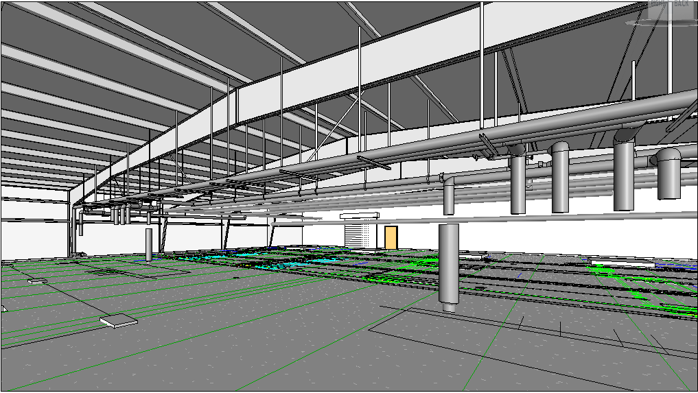
Thanks MBSTEVE,
Very impressive drawing. Having worked with a similar warehouse gut job with completly new utilities added to the structure i can appreicate the amount of work that your image shows and the use to all of those that involved. I think the architect moved a Gas 3" overhead gas pipe 3 times to fit some architectural ceiling features.
an additional challenge is getting the utility lines (set up as families for reporting possibliies in spreadsheets) to curve in plan (say telco and power underground). I am using an adapted family and dragging the handles once added to the drawing.
again,
thanks for your comments,
jw
|
This user is offline |
|
|
|
Similar Threads |
|
Avatech utilities : how to use them |
Revit Building >> Technical Support
|
Wed, Dec 12, 2007 at 6:30:40 PM
|
3
|
|
Modeling Site Utilities (i.e., SS, SD, Waterline....) |
Revit Building >> Technical Support
|
Wed, Mar 30, 2011 at 9:17:08 PM
|
3
|
|
Avatech Utilities for Revit |
General Discussion >> Revit Project Management
|
Mon, Aug 24, 2009 at 11:54:21 AM
|
3
|
|
Making railing balusters visible in plan |
Revit Building >> Technical Support
|
Tue, Mar 14, 2017 at 7:27:15 AM
|
5
|
|
Enlarged plan of x-ref |
Revit Building >> Technical Support
|
Tue, Nov 29, 2005 at 1:25:54 PM
|
5
|
|
|
Site Stats
Members: | 2161655 | Objects: | 23325 | Forum Posts: | 152479 | Job Listings: | 3 |
|