|
Forums >> Revit Structure >> Technical Support >> CMU wall reinforcement and detailing
|
|
|
active
Joined: Mon, Oct 27, 2008
23 Posts
 |
How is everybody detailing CMU wall reinforcing bars? Are folks modeling the bars or simply drawings the bars with detail lines in each section cut through a CMU wall? I have an 8" CMU wall with #4 bars @ 24" at the wall centerline. I can model a #4 bar in the wall and set the maximum spacing to 2'-0". However depending on where I cut another section through that wall, the rebar may not show up in the section. Therefore I end up having to draw a bar in the wall with detail lines. Also on the subject of CMU walls in section, our office prefers to show the CMU in greater detail than the standard crosshatch fill pattern. We show face shells and mortar joints. Right now we are accomplishing this by using a repeating detail of the CMU Section detail item in every section that cuts through a CMU wall. Anyone else showing CMU walls this way, or have a better way of showing the CMU in greater detail? I'm working in Revit Structure 2011.
|
This user is offline |
|
 |
|
|
|
active
Joined: Thu, Oct 21, 2010
102 Posts
 |
This really depends on what you are trying to do. Many companies are just using detail lines because they are not producing shop drawings so they do not need to schedule the bars or anything for quantities and such. The firm I am at uses detail lines for the CDs and then models it for the shop drawings (a little redundent I think). The rebar tool is still not ideal as it has some glitches and tends to try to snap to everything giving you fractional bar lengths. There really should be no reason that you are not seeing the bars when you cut. If you are going to show the model bars in one view, I would recomend doing the same in most views that show that set of bars...I would not recommend doing it half and half. Use one or the other, and limit the other for special cases.
|
This user is offline |
|
|
|
active
Joined: Mon, Oct 27, 2008
23 Posts
|
Hi, thanks for the response. You are correct, after placing modeled bars in the CMU wall with a 2'-0" spacing they do appear in any section cut through that wall. I must have made a mistake earlier, modeling the bars is working fine for me. My firm does not produce shop drawings, only construction documents. Do you show your CMU walls in section as just the typical CMU crosshatch? My firm shows the CMU face shells and mortar joints in section. To do this I draw a repeating detail of the Revit CMU detail component over the CMU wall in section. Unfortunately this covers up the modeled reinforcing and Revit does not have an option to bring the reinforcing to the front. I supposed I am stuck with using a reapeating detail for the CMU in section and detail lines for the reinforcing.
|
This user is offline |
|
|
|
active
Joined: Thu, Oct 21, 2010
102 Posts
|
Could you post a picture of how Revit is displaying your CMU and how you would like it to show? I will take a look and see how to work around it.
|
This user is offline |
|
|
|
active
Joined: Mon, Oct 27, 2008
23 Posts
|
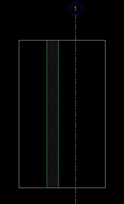
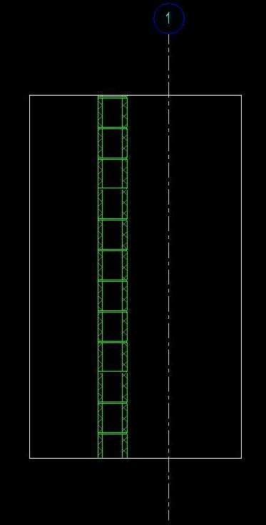
The first picture is of the standard CMU crosshatch for CMU in section. The second picture is the desired look of the CMU in section for my firm. I used a repeating detail of the CMU detail component.
|
This user is offline |
|
|
|
active
Joined: Thu, Oct 21, 2010
102 Posts
|
Ok, so the way that I would do this is to first shut off wall visiblity or at least make the cut pattern not visible in section for the wall, then go in and modify your detail component. In there it looks like you have 2 or 3 filled regions/masking regions. All you should need to do is delete what ever is masking the wall in the center, and make the outer hatchings transparent if they are not already. Hope that makes sense...let me know if it doesn't. If not...post up your detail component and I will take a look and fix it.
|
This user is offline |
|
|
|
site moderator|||
Joined: Tue, May 16, 2006
13079 Posts
 |
Use a repeating detail....
|
This user is offline |
|
|
|
active
Joined: Thu, Oct 21, 2010
102 Posts
|
That is what he is doing, but the detail is covering up his bars, so he needs to change the detail component so that it does not cover his bars.
|
This user is offline |
|
|
|
active
Joined: Mon, Oct 27, 2008
23 Posts
|
Thanks gdoherty, that is a simple and effective solution. Using the repeating detail is nice, but I have to do it for every section cut through a CMU wall. It would be great if I could make the repeating detail into a fill pattern type and assign it to my cut pattern for CMU walls. However the fill pattern would have to recognize the bottom corner of the CMU wall as the start point for the pattern to make sure masonry coursing is shown correctly. Do you think this is possible?
|
This user is offline |
|
|
|
active
Joined: Thu, Oct 21, 2010
102 Posts
|
The only way I could really see this would still not give you your grout lines, and that would be to create a CMU wall as three parts, the inner face, outer face, and the inside and give the two faces the pattern you want and leave the cut pattern of the inner part blank. This would look odd in plan though how ever. The issue is really that a cut pattern is a cut pattern Revit does not distiguish between if you are cutting in section versus cutting in plan.
|
This user is offline |
|
|
|