Forums
|
Forums >> Revit Structure >> Technical Support >> draw order in revit 2010
|
|
|
active
Joined: Wed, Sep 8, 2010
7 Posts
No Rating |
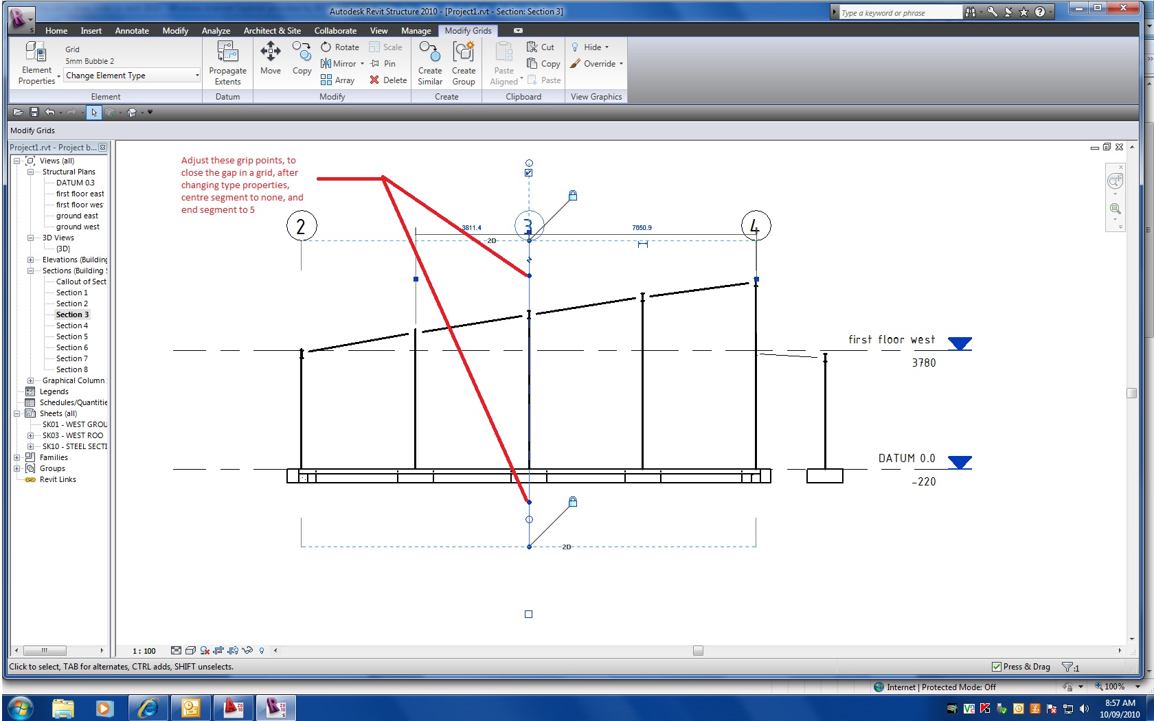
Hi every one, I have just made the switch from autocad to revit, so far loving it, i just have one small problem, Draw order, i will attach a screen shot of what i mean, but basically, when i do elevations of steel, the grid line is coming out on top of my heavy steel line, representing the column. See attached. Now i know i cant do this anymore and compare revit to autocad, but one last time, in autocad there is the draw order command, is there such a thing in revit? See attached it will explain better, i want to see a thick line representing a column not the grid. Thanks in advanced. oh yeah this is a photo of my print out.
Edited on: Wed, Sep 8, 2010 at 7:40:44 PM
|
This user is offline |
|
 | |
|
|
active

Joined: Thu, Mar 17, 2005
1231 Posts
 |
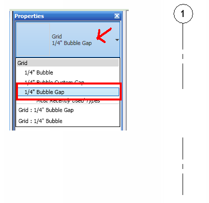
Grid lines and level lines in REVIT are bullies and they like to stay on top. Even if you do a graphics override and make them lighter they still block out what's behind them. You cannot use draworder with grid or level objects. Try making the grid line a 'grid with gap' type as shown in the attached image. Also try using 'alt-prtsc' on your keyboard then paste to paint etc . . . . to do screen captures instead of taking a picture ?
-----------------------------------
.
FULL 'DOWNLOAD ACCESS' to all 850+ CADclips videos for only $150
|
This user is offline |
View Website
|
|
|
active
Joined: Sat, Aug 11, 2007
4 Posts
No Rating |
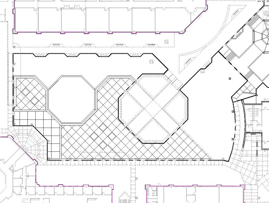
How about drawing lines over DWG links? I'm showing a siteplan where the existing buildings and site elements are on the DWG link. I want to draw a scope of work line to outline an area on the site where new sitework will be included in my project. The lines all show on in Revit, but when I print, some of the lines show and others do not show--not a consistent result. How do I get the linework to always be on top of the link? (attached image is what it looks like in Revit and what I want it to print like.)
|
This user is offline |
View Website
|
|
|
active
Joined: Thu, Mar 17, 2005
1231 Posts
|
Hmm, that's tricky. Could be plotter driver specific because REVIT shows it correctly. Make sure the dwg doesn't have 3d linwork above your linework. Place your linework as high as possible within the view range / cut plane. Maybe create a new reference plane / workplane up above the floor level for your linework. Then you may have to start dorking around with the imported dwg object style / vg overrides. ie: find the culprit layer and turn it off.
-----------------------------------
.
FULL 'DOWNLOAD ACCESS' to all 850+ CADclips videos for only $150
|
This user is offline |
View Website
|
|
|
active
Joined: Wed, Sep 8, 2010
7 Posts
No Rating |
Hello Everyone. dgcad, thanks for your comment, i didnt do a print screen, cause it looks ok on screen, i wanted to show people what it looked like after printing. Anyway when i was looking for 1/4 bubble gap which i couldnt find, i came across how to solve this problem. I went to element properties, type properties, a dialog box comes up, in the dialog box there is an option that says centre segment, i changed this to none. i also changed the end segment length to 5, this pulls the grid outside the column. there is also then one more thing i found, you can click on the grid an adjust the distance of the gap of the grid with no centre segment. refer attached. This has solved my problem and im very happy, its a long way around though, so hopefully autodesk fixes this in the new versions. im on 2010, i wonder if its the same in 2011. If not i might have to, include these settings in my template folder or something. Thanks again dgcad hope this helps everyone out there aswel. Until next time.
|
This user is offline |
|
|
|
active
Joined: Thu, Mar 17, 2005
1231 Posts
|
. Good work. What you describe is in fact the out of the box Grid with Gap which I mentioned.
-----------------------------------
.
FULL 'DOWNLOAD ACCESS' to all 850+ CADclips videos for only $150
|
This user is offline |
View Website
|
|
|
active
Joined: Wed, Sep 8, 2010
7 Posts
No Rating |
Hi dgcad i did it your way but when u change the grids in elevations it changes in plans, then the plans look like crap, arghhhhhhhhhhhh, maybe its not meant to be haha. Maybe i have to change the grids to no centre segment and draw a line in plans, where the gap is, so it doesnt show up in elevations. So annoying. It does work but Surely this is not the only way, Anyway thanks again in advance.
Edited on: Thu, Sep 9, 2010 at 9:21:23 PM
|
This user is offline |
|
|
|
active
Joined: Fri, Jun 12, 2009
38 Posts
 |
hey guys, I'm in 2012 having the same issue with grid lines over top of beams. I did the center segment as none and was able to pull back what I want at both ends but you can't seem to do this with curved grids. They seem to take on different properties even though they are the same as the normal line segment grids. I need to show both ends of the grid and don't want to draw in line work to get the other end. Any thoughts on the curved grids?
|
This user is offline |
|
|
|
Similar Threads |
|
Draw Order for Revit? |
Revit Building >> Technical Support
|
Mon, Jun 21, 2010 at 2:49:31 PM
|
0
|
|
Draw Order for Wall Sections? |
Revit Structure >> Technical Support
|
Tue, May 18, 2010 at 11:32:30 AM
|
0
|
|
Draw Order in Family Editor |
Community >> Newbies
|
Wed, Aug 28, 2013 at 3:07:31 PM
|
1
|
|
draw order |
Revit Building >> Technical Support
|
Wed, Aug 20, 2008 at 8:26:33 AM
|
3
|
|
Draw order of linked DWGs |
Revit Building >> Technical Support
|
Thu, Jun 21, 2007 at 9:14:00 AM
|
2
|
|
|
Site Stats
Members: | 2161655 | Objects: | 23325 | Forum Posts: | 152479 | Job Listings: | 3 |
|