Forums
|
Forums >> Revit Building >> Technical Support >> Creating a Site
|
|
|
active
Joined: Mon, Apr 5, 2010
26 Posts
 |
Cannot even start a site model. I have imported an autocad site plan and I am hoping to be able to "trace" the CAD lines in order to create my 3D site model in Revit. Thanks.
|
This user is offline |
|
 | |
|
|
site moderator|||
Joined: Tue, May 16, 2006
13079 Posts
 |
Don't do that! Look in your HELP : "Creating a Toposurface from Imported 3D Data"
|
This user is offline |
|
|
|
active
Joined: Mon, Apr 5, 2010
26 Posts
|
The file I am trying to reference the site dimensions, boundaries, topograpgy, ect. from is not 3D data... I want to do this without 3D data, possible?
|
This user is offline |
|
|
|
active
Joined: Mon, Apr 5, 2010
26 Posts
|
or, can I reference in a pdf even, something to "trace"?
|
This user is offline |
|
|
|
site moderator|||

Joined: Tue, May 22, 2007
5921 Posts
 |
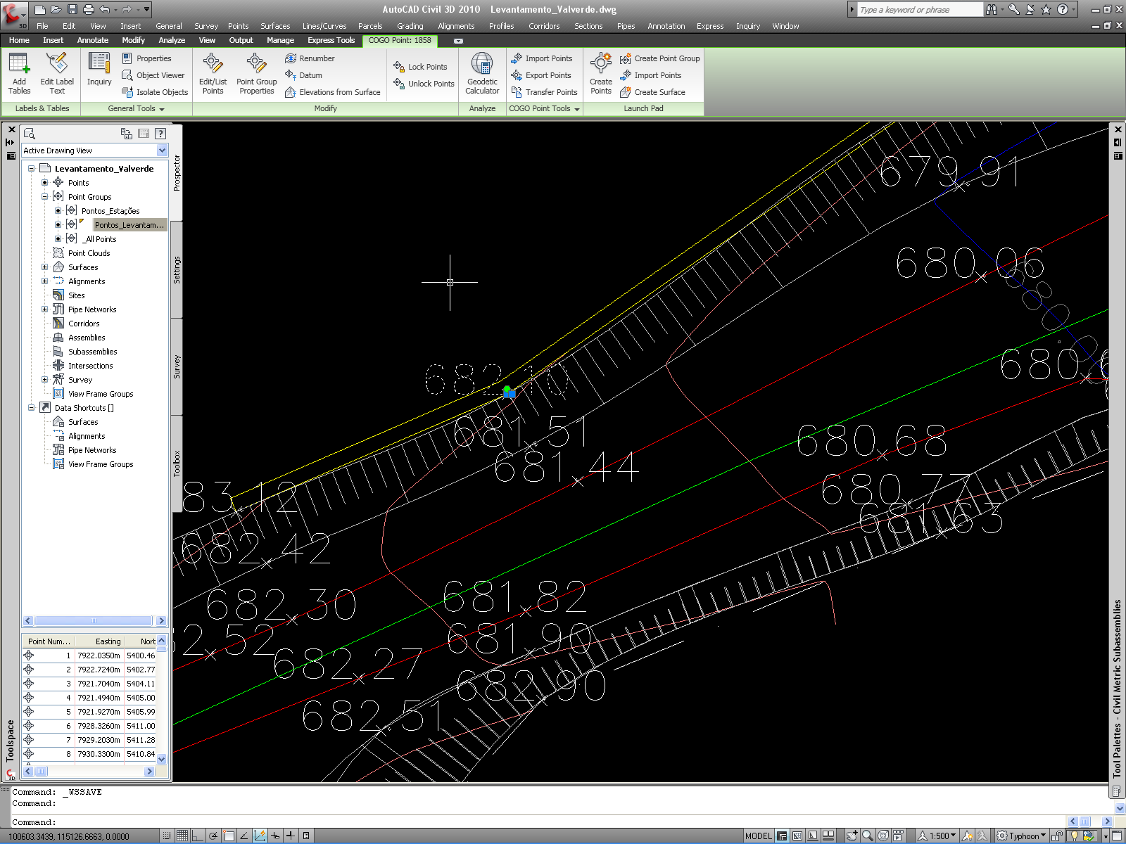
Do you have the "Z" (elevation) Labels (text) in Autocad or points with Z ???
-----------------------------------
I Hope and I Wish to LEARN more, and more, and more.... REVIT |
This user is offline |
|
|
|
site moderator|||
Joined: Tue, May 16, 2006
13079 Posts
|
Sure - you can just do what you were asking but there is a much easier way! Look ... If this is a CAD file, and the topography (topo lines) are polylines, they should be set to elevations. If not, then edit the cad file and set them. Also make sure the topo lines are on a seperate layer from other data, then follow the HELP. Go ahead and copy (trace) your property lines and other linework as you need it ... or just use the CAD file in appropriate views. REVIT's topography lines don't work well so if you need a drawing with topo-lines, use the CAD.
|
This user is offline |
|
|
|
active
Joined: Mon, Apr 5, 2010
26 Posts
|
typhoon, im not sure what you mean. help? wwhub - err, im not certain on how to set polylines to elevations in autocad, but i'll give it a shot.
|
This user is offline |
|
|
|
site moderator|||
Joined: Tue, May 22, 2007
5921 Posts
|
What i'm talking about (like you can see in the image) is the LABEL of the Elevation point, it's ONLY text..... do you have that in your CAD file?
Edited on: Fri, Apr 9, 2010 at 11:22:59 AM
-----------------------------------
I Hope and I Wish to LEARN more, and more, and more.... REVIT |
This user is offline |
|
|
|
active

Joined: Fri, Sep 22, 2006
759 Posts
|
I'm going to assume that your site is really not that complicated. First create the boundary using the bearings and distances table in Revit. You can do this from a paper map. Second do not try to follow contour lines Revit does not work like that. On the Site tab use the create points button and place point elevations matching the locations which you can scale on the map. Probably just a few point elevations are required. Revit will create the contours. Read your help menu about Creating toposurface. Good Luck
|
This user is offline |
|
|
|
active
Joined: Mon, Apr 5, 2010
26 Posts
|
typhoon - yes
|
This user is offline |
|
| |
|
|
active
Joined: Mon, Apr 5, 2010
26 Posts
|
These are the instructions from the HELP (i already have the DWG file imported): To create a toposurface from an imported DWG file - Click the Toposurface tool on the Site tab of the Design bar.
- On the Design bar, click Use Imported > Import Instance.
- Select the DWG file.
- Select the layers to add points from.
- Click OK.
- Click Finish Surface.
I follow, until....3. I cannot "select" the DWG file. It seems to be unresponsive.
|
This user is offline |
|
|
|
site moderator|||
Joined: Tue, May 16, 2006
13079 Posts
|
You need to import the file while you are in the topo command.
|
This user is offline |
|
|
|
site moderator|||
Joined: Tue, May 22, 2007
5921 Posts
|
I ask you: "What i'm talking about (like you can see in the image) is the LABEL of the Elevation point, it's ONLY text..... do you have that in your CAD file?" - and you said: "typhoon - yes" So.... watch the video: http://www.megaupload.com/?d=QK9WS65N BUT first download and save the LISP routine into a folder...
Edited on: Wed, Apr 28, 2010 at 6:38:44 AM
-----------------------------------
I Hope and I Wish to LEARN more, and more, and more.... REVIT |
This user is offline |
|
|
|
active
Joined: Mon, Apr 5, 2010
26 Posts
|
Thank you! this is going to be so helpful
|
This user is offline |
|
|
|
active

Joined: Sun, Mar 27, 2005
208 Posts
 |
lots of discussion here. i'll just add a few pointers if it helps. topos are not ideal in revit yet, but one day they'll be better. - if using a cad file to create a topo, make sure it is imported into the model, not just current view. it must be a model object otherwise revit struggles to 'see' the 3d points.
- survey data, especially contours, takes legal precedence over any contours revit can show. so i often use the survey drawing as an underlay in site plans, and sometimes turn off the topo.
- if the survey file has no z coordinates, it is usually not a huge ask to create the topo by putting your own points on the topo by following contours and single points.
- selecting the layers in the cad file to create the topo is a bit hit and miss i find. after a bit of discussion, our surveyors now have added a couple of mesh layers which work really well. in 3d, you can see them, and it becomes easy to check what you are doing with the revit topo. maybe ask your surveyor about this.
- cad files will have points that are not on the ground, so it is often the case that you need to delete some. this gets rid of those weird peaks and valleys. our surveys give us roof and floor points when dealing with existing buildings, so watch out for that.
- it is safer to use the select arrow over the survey boundaries for creating property lines, if you have a survey, as that is legal data. but there is a trick. if you change view property to true north, import the cad file (which usually has north up the page), then create the property lines, they will report their bearings as correct, if you then change the view to project north. i now ensure i have a project with correct true north from the start, as it keeps things correct right from the start.
- never ever use detail or model lines to emulate property lines. well that is my take on it. property lines have lots of uses in revit, one being able to do area assessments such as site cover. another is perimeter.
- when you create topos in revit it closes the outer points in a straight line. so if you end up with a concave position of points the topo is actually incorrect, but revit knows no better. insert points to fix this, or what we do is get the surveyor to go 1m past boundaries and we sometimes split off the 'incorrect' ones. this is so important if you need to get accurate height lines at boundaries.
- we obtain original natural ground meshes from our surveyor, in addition to existing ground. so we can put 'glass' topos at the height restriction positions. if you need to do this, try creating topos in a separate revit file, and then link it. that way you can adjust poche in the other file, but linked files are so useful anyway.
hope some of that helps.
|
This user is offline |
View Website
|
|
|
Similar Threads |
|
Advice on creating a site plan |
Revit Building >> Technical Support
|
Mon, Jul 12, 2010 at 5:04:03 PM
|
8
|
|
First Time Multi-Bldg Site |
General Discussion >> Revit Project Management
|
Fri, Nov 30, 2012 at 7:38:45 AM
|
7
|
|
Creating CD's from a file with several linked buildings? |
Community >> The Studio
|
Mon, Sep 18, 2006 at 9:33:23 AM
|
2
|
|
creating a site the shape of a capital E |
Revit Building >> Technical Support
|
Wed, Jun 23, 2010 at 7:10:47 AM
|
1
|
|
Walls from multiple floors above showing in site plan |
Revit Building >> Technical Support
|
Wed, Oct 3, 2012 at 9:23:52 PM
|
4
|
|
|
Site Stats
Members: | 2161655 | Objects: | 23325 | Forum Posts: | 152479 | Job Listings: | 3 |
|