|
|
|
Home | Forums |
Downloads | Gallery |
News & Articles | Resources |
Jobs | FAQ |
| Join |
Welcome !
|
9 Users Online (7 Members):
Show Users Online
- Most ever was 626 - Mon, Jan 12, 2015 at 2:00:17 PM |
Forums
|
Forums >> Revit Building >> Technical Support >> How to show a 'diagonal cross' when you cut timber beam/plate?
|
|
|
active
Joined: Mon, Jun 26, 2006
58 Posts
 |
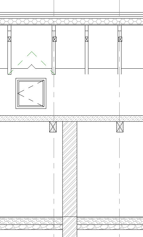
I am trying to create a family for bearers and joists so when I do sub floor layouts I can construct them in 3d and have my sections then draw properly. When you cut through a top/bottom plate or a bearer/joist you show it with a cross from each diagonal corner. Similar to the crosshatch but it needs to be accurate from corner to corner when sizes change. How do I add this to the 'cut pattern' option in materials or do I somehow draw it as a symbolic line in the family editor? It is not a repeating symbol like the 'cut patter' hatch options, more accurate linework. Not much point in creating 3d elements for my section if they cannot display correctly and I have to draft over them anyway. Will attach picture if you dont understand. Thanks
|
This user is offline |
|
 | |
|
|
active

Joined: Sun, Feb 17, 2008
197 Posts
 |
Create a section within the family and you should be able to draw however you want the section to look in the model within the family section.
-----------------------------------
J. Allen Ball Revit Architecture 2010 Certified Professional |
This user is offline |
|
|
|
site moderator|||

Joined: Tue, May 22, 2007
5921 Posts
|
Edit the family and in a section view create the symbolic lines (cross lines) but don't forget to attach the endpoints of the symb. lines to the lines of the beam...
-----------------------------------
I Hope and I Wish to LEARN more, and more, and more.... REVIT |
This user is offline |
|
|
|
active

Joined: Thu, Mar 17, 2005
1231 Posts
 |
Hmmm, detail lines in a family are hosted by a work plane are they not? For this to work you would have to locate the section in the project in the exact same place as in the family or it would at least have to be right in front of the family detail lines and you would also have to set the view to 'wireframe' in oder to see the detail lines in the family. I think you need to do it the way REVIT intended. Use detail lines within the section view itself in the project. Maybe make it a group to speed things up. Takes two seconds to drag the 'X' group into the view. Keep them in your project template file.
-----------------------------------
.
FULL 'DOWNLOAD ACCESS' to all 850+ CADclips videos for only $150
|
This user is offline |
View Website
|
|
|
active
Joined: Wed, Oct 23, 2019
0 Posts
No Rating |
I can see this thread is ten years old now. Still I managed to solve the same problem . However when it comes to rafters I can't get the symbol lines to show. The rafters are timber members at an angle and when shown in section don't show the cross symbol.
Would anyone have an idea how to solve this one,
Thanks in advance.
|
This user is offline |
|
|
|
Similar Threads |
|
Structural beam won't show in elevation |
Revit Building >> Technical Support
|
Fri, Aug 12, 2005 at 5:22:08 PM
|
3
|
|
Diagonal cross net railing panel |
Revit Building >> Technical Support
|
Mon, Mar 4, 2019 at 9:52:39 AM
|
1
|
|
LENGTH OF TEXT IN 'TYPE' IN BEAM SCHEDULE |
Revit Structure >> Technical Support
|
Sat, Nov 6, 2010 at 8:37:23 AM
|
3
|
|
Detailing a Beam Saddle at Valley Beam |
Revit Structure >> Technical Support
|
Wed, Jan 26, 2011 at 12:15:21 PM
|
2
|
|
How would I go about creating a timber frame? |
Revit Building >> Tips & Tricks
|
Fri, Feb 10, 2006 at 3:49:50 PM
|
1
|
|
|
Site Stats
Members: | 2161655 | Objects: | 23325 | Forum Posts: | 152479 | Job Listings: | 3 |
|