|
|
|
Home | Forums |
Downloads | Gallery |
News & Articles | Resources |
Jobs | FAQ |
| Join |
Welcome !
|
4 Users Online (2 Members):
Show Users Online
- Most ever was 626 - Mon, Jan 12, 2015 at 2:00:17 PM |
Forums
|
Forums >> Revit Structure >> Technical Support >> Cutouts in wall and floor joints
|
|
|
active
Joined: Tue, Sep 23, 2008
42 Posts
No Rating |
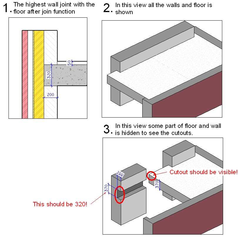
Hello everyone... I attached a picture where everything is shown. Does anyone have some comments about the text in red? Could it be that REVIT avoids such mistakes?
|
This user is offline |
|
 | |
|
|
site moderator|||
Joined: Tue, May 16, 2006
13079 Posts
 |
You are asking REVIT to do somethings it was not meant to do! Revit will show the cleanups correctly in section. It will also show the items correctly in 3D. If you want it to show correctly in a 3D section, then build your floor as two components! Slab only and topping/insulation seperate.
|
This user is offline |
|
|
|
active
Joined: Tue, Sep 23, 2008
42 Posts
No Rating |
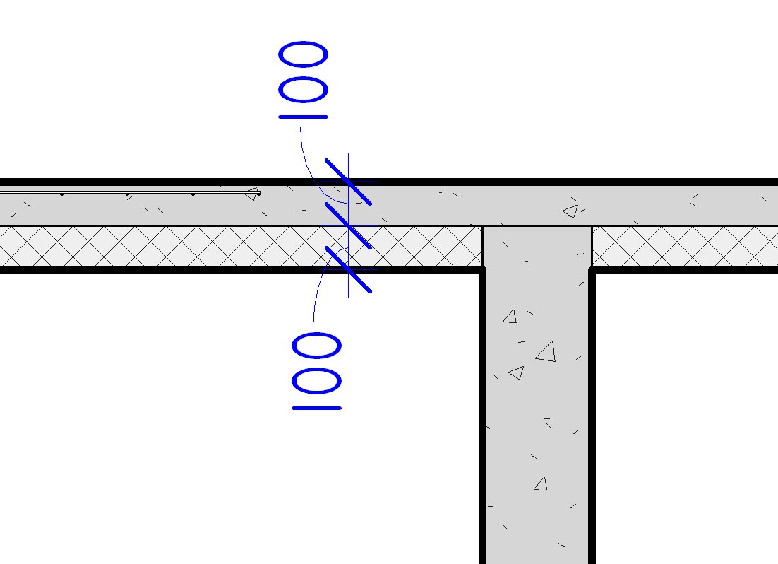
I guess the wish list should be supplemented. Remember the previous thread we talked about wrong section view, i think that this wrong view generated by revit is because of these coutouts.I revit would make these cutouts right, the the section view also would be right, dont you think so? And speaking about what was meant to do... My opinion is that we use the "STRUCTURAL" version of REVIT, so they must make things appear right. Architects dont need such detailing, so this is why they use "ARCHITECTURAL" version.. We are making complex designs, so we need good tools and relyable ones. I had one good example form life, where this mistake of REVIT almost cost us extra days in worksite. The thing was, that we had a concrete foundation wall that was joined with the concrete floor. The floor had insulation layer 100mm and then concrete layer 100mm above. So in the section view concrete wall joined to the concrete part of the wall and everything looked right, but when placing spot dimensons in the plan, the actual top level of wall should be "-100mm" but the spot dimension showed "-200" (see the picture of section) because of these cutouts. So I thik this is huge mistake that REVIT guys have missmatched..
|
This user is offline |
|
|
|
Similar Threads |
|
Modified wall layers (Sheating) need cutouts for openings and extensions |
Revit Building >> Technical Support
|
Tue, Sep 23, 2014 at 8:45:35 AM
|
1
|
|
Floor+beam and wall joints |
General Discussion >> Revit Project Management
|
Wed, May 12, 2010 at 10:46:56 PM
|
0
|
|
vertical joints in hosted wall sweep? |
Revit Building >> Technical Support
|
Mon, Aug 13, 2007 at 3:37:15 PM
|
0
|
|
Wall and floor joints |
Revit Structure >> Technical Support
|
Tue, Dec 30, 2008 at 10:42:08 AM
|
13
|
|
Concrete control joints |
Revit Building >> Technical Support
|
Thu, Mar 31, 2016 at 1:52:27 PM
|
11
|
|
|
Site Stats
Members: | 2161655 | Objects: | 23325 | Forum Posts: | 152479 | Job Listings: | 3 |
|