|
|
|
Home | Forums |
Downloads | Gallery |
News & Articles | Resources |
Jobs | FAQ |
| Join |
Welcome !
|
11 Users Online (9 Members):
Show Users Online
- Most ever was 626 - Mon, Jan 12, 2015 at 2:00:17 PM |
Forums
|
Forums >> Revit Building >> Technical Support >> Supported Roof - Ideas Needed
|
|
|
active
Joined: Mon, Aug 18, 2008
2 Posts
No Rating |
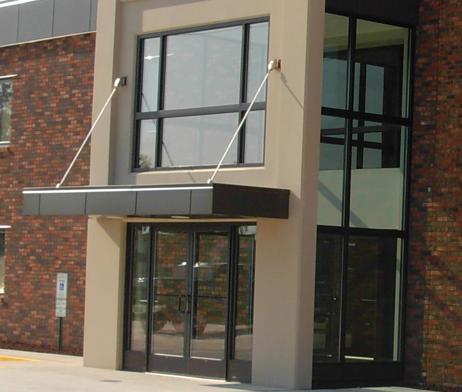
Hello all - Revit Architecture 2009 Question I have a 4'x12'x1' steel roof that has two support cables attached to the roof and the wall (see attached picture). I have the roof done, but I am looking for ideas how to make the support cables. Let me know what you think. Thanks!!! Ryan
Edited on: Fri, Oct 3, 2008 at 1:13:11 PM
|
This user is offline |
|
 | |
|
|
site moderator|||
Joined: Tue, May 16, 2006
13079 Posts
 |
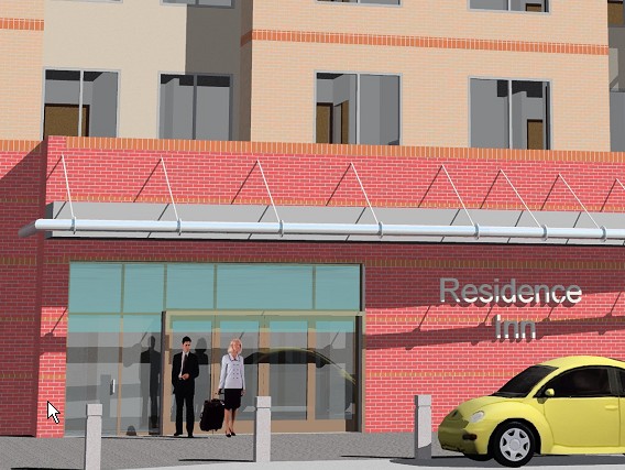
Attached is a study sketch I did back in 8.1. The rods are simple extrusions.
|
This user is offline |
|
|
|
active
Joined: Mon, Aug 18, 2008
2 Posts
No Rating |
I have never done an extrusion before. Can you provide a little more direction? Thanks!!! Ryan
|
This user is offline |
|
|
|
site moderator|||
Joined: Tue, May 16, 2006
13079 Posts
|
That's way too general of a question. Start my looking up extrusion and in-place families in your REVIT help. Also look at some of the traing videos listed in this thread http://www.revitcity.com/forums.php?action=viewthread&thread_id=13280
|
This user is offline |
|
|
|
active
Joined: Mon, Dec 17, 2007
83 Posts
 |
I made a quick generic model family of a tension rod that does what you need. This is a non-hosted component. You will load it in and then you will need to input how far to offset it from the reference level. I have made the tension rod with two instance parameters: Height and Projection. The height is the vertical distance from the bottom clevis to the top clevis and the projection is the horizontal distance between thr two clevises. You might want to take a look at how I modeled this. I drew reference planes and assigned parameters to the horizontal and vertical dimensions. I then drew a reference line. Next, I did a sweep and picked the reference line as the path. The purpose of this method is that the sweep will update when the parameters are changed for the height and projection. I then made the clevis by modeling an extrusion from the side and then the part of the clevis that is attached to the endo of the tension rod is made as a sweep blend. I picked the reference line as the path for the sweep and then shortened the path up to one foot long. I then drew to profiles at each end of the path to give the tapered appearance to the clevis. If you really wanted to go crazy on parameters, you could assign parameters to nearly all of the dimensions on this thing. I hope that helps.
|
This user is offline |
|
|
|
active
Joined: Mon, Dec 17, 2007
83 Posts
|
I have made a few more things about the family parametric. You can now adjust the radius of the tension rod which also adjusts the radius of the clevis.
|
This user is offline |
|
|
|
Similar Threads |
|
walls wont attach to new roof |
Revit Structure >> Technical Support
|
Mon, Nov 18, 2013 at 3:57:45 PM
|
8
|
|
Element is Not Supported |
General Discussion >> Revit Project Management
|
Fri, May 17, 2013 at 12:17:40 PM
|
1
|
|
Adding a Portico to a Roof [ 1 2 ] |
Community >> The Studio
|
Sun, Aug 17, 2014 at 3:39:03 AM
|
16
|
|
multiple instances of the same view in sheet not supported |
Community >> Newbies
|
Tue, Dec 4, 2012 at 12:40:35 PM
|
4
|
|
Irregular residential roof |
Revit Building >> Technical Support
|
Mon, Aug 27, 2012 at 3:55:40 AM
|
12
|
|
|
Site Stats
Members: | 2161655 | Objects: | 23325 | Forum Posts: | 152479 | Job Listings: | 3 |
|