Forums
|
Forums >> Revit Building >> Technical Support >> Canopy Stud buidouts
|
|
|
active
Joined: Sat, Aug 2, 2008
10 Posts
No Rating |
What is the process with the wall styles (old adt guy) to create projected framed canopies on a retail building for example, that miter back to the main wall. I have done this in adt for years with variable width chase walls, but I'm having a problem figuring this out in Revit. I've been searching the web for examples but the closest I've found are brick cavity walls. Need brain dump on advanced wall methods. Thanks, David
|
This user is offline |
|
 | |
|
|
active

Joined: Thu, Mar 17, 2005
1231 Posts
 |
Hey David, I too am an old ADT / Softdesk Auto Architect guy. Once you get going with REVIT you'll never want to use ADT again. (ok maybe you'll miss the tool palettes). I'm sure I can help you but I don't quite understand what you want. Can you provide a sketch or image of some sort showing what you want as a finished product? I'm not 100% sure what a "projected framed canopies " is? Even a photograph of one will do. Daryl Gregoire REVIT Training Videos
-----------------------------------
.
FULL 'DOWNLOAD ACCESS' to all 850+ CADclips videos for only $150
|
This user is offline |
View Website
|
|
|
active
Joined: Sat, Aug 2, 2008
10 Posts
No Rating |
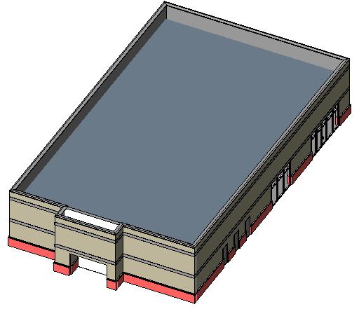
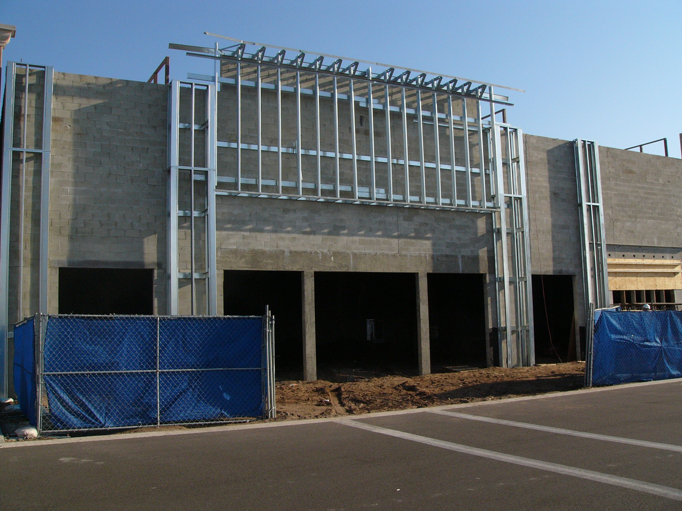
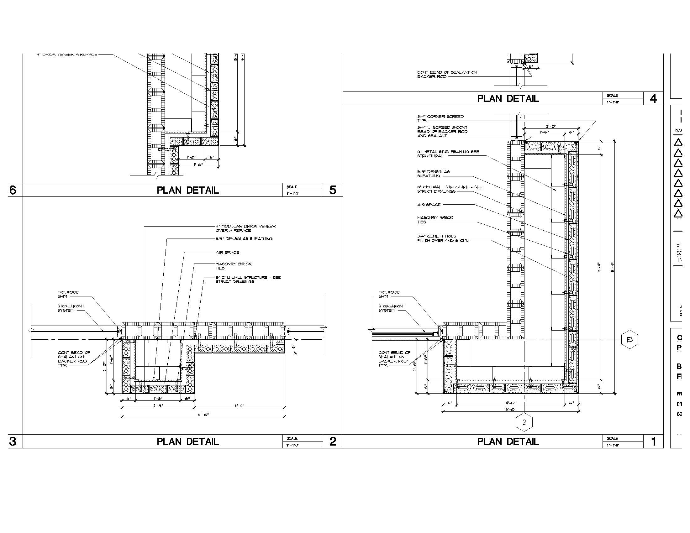
This is the type of construction I'm trying to figure out how to do in revit. In adt I would have created a wall style that was then cut by an opening using a endcap profile for the jambs. The masonry openings in the photo are the locations of the storefront system. What is the right procedure to creating cavity framed wall types? And variable depth ones? I had to use individual revit wall types instead of say a 2 foot thick framed wall that could be used as in the photo. And sometimes in these designs, there is a buildout with an opening and no storefront only stucco. At the base like in my posted revit jpg, there is a stone, or brick base that has to return back to the main wall. Thanks, David
|
This user is offline |
|
|
|
site moderator|||

Joined: Tue, May 22, 2007
5921 Posts
 |
Hi, i think you must create that with structural columns, beams and braces and then you can put your "Wall" (2 foot thick framed wall) around the model.
Edited on: Sun, Aug 3, 2008 at 7:54:58 AM
-----------------------------------
I Hope and I Wish to LEARN more, and more, and more.... REVIT |
This user is offline |
|
|
|
active
Joined: Thu, Mar 17, 2005
1231 Posts
|
Thanks for the great photo David. Nice inside look for junior designers to see. I will fully and completely disagree with Mr. Typhoon. Specifically as a beginner, you would NEVER model every peice of steel around a building like that with structural columns, beams and braces any more than you would model each and every framing member in a revit model. Perhaps as your revit skills improve (to a much higher level) you may start to model more of the internal framing. I would like to see a finished version of that facade but I would start with a basic inplace (massing) family and cover the internal framing with traditional 2d detaining. Once you get that process under your belt and repeat the exercise you may find better ways (and you will). Someone who does lots of this type of design drafting would have a Wall Catagory external family (.rfa) with parameters (easily done). You would simply place the facade family in the model and change the dimensions. Detailing still done in 2d. If you can post a finished version of this I can make you a video of how it's done. Please forgive Mr. Typhoon for his incorrect answer as he has decided to impose on (and stalk) any conversation I have on this site and provide his worthless 2 cents. Which is fine by me because I will simply CRUSH him with my knowledge but it's not fair to mislead the other readers in his quest to annoy me. Moderators can you please get a grip on this guy.
-----------------------------------
.
FULL 'DOWNLOAD ACCESS' to all 850+ CADclips videos for only $150
|
This user is offline |
View Website
|
|
|
site moderator|||
Joined: Tue, May 22, 2007
5921 Posts
|
Well PROARCH1, if you still want to live in the past you must keep working in CAD, because REVIT is 3D and CAD is basicly 2D, so, you must do a choise: I want start working in Revit? or still with CAD? because in CAD you can create also your blocks with 2D details and you don't waste time to do the model in 3D. After the model is done, you have your Plans, Sections, Elevations, Callouts, and so one. Work 3D not 2D.Good Luck.
-----------------------------------
I Hope and I Wish to LEARN more, and more, and more.... REVIT |
This user is offline |
|
|
|
active
Joined: Thu, Mar 17, 2005
1231 Posts
|
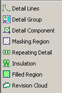
I'm not sure what to say. If David is a structural framing supplier then he should learn to model all framing objects in full 3d. Agreed. Otherwise you are leading him down the wrong path as a novice revit architectural user. Model the canopy in 3d by massing, or walls, or inplace families or external families. It doesn't matter. Complete the contract documentaion by using the revit detailing tools with the sections and callouts of the 3d model. Done and Done. That's how you learn. Not by modeling every brace and stud in the building. FYI - 'CAD' means 'Computer Aided Drafting'. There is no reference to 3d, 2d, or software developer. Make your choice 2d or 3d ? Hello, REVIT was designed from the very beginnning to use both. Perhaps you are not familier with the tools in the attached image (to mention only a few). Have you ever tried the 'Edit Cut Profile' tool ? Are you aware of the new efficient methods of managing /storing / importing and exporting 2d detail views in REVIT ? This is a real world user with real world time lines.
-----------------------------------
.
FULL 'DOWNLOAD ACCESS' to all 850+ CADclips videos for only $150
|
This user is offline |
View Website
|
|
|
active
Joined: Sat, Aug 2, 2008
10 Posts
No Rating |
I don't know who typoon is. Daryl I appreciate you repsonses. The photo I attached was the constructed structure. I am trying to document the symbolic ie: Plan and elevations delineated as typical architects do, the plan, refelected ceiling, sections and details as Revit is designed to facilitate. What I have found out through Revit so far is that openings that should display as dashed above (soffits), have to be draw in using the line tool. A wall that has a brick veneer with stud backup can't have a variable stud location ie depth of pilaster, cavity wall etc. off of the main wall structure and need individual styles to define multiple depths. Doors, windows have to be created with the symbolic dashed lines above in the door style. And or the thresholds, sill also. Is this correct? Or is there another work around. Thanks, David
|
This user is offline |
|
|
|
active

Joined: Thu, Dec 13, 2007
135 Posts
|
Hey, if you dont need to schedule the structural elements, you could model the studs as a curtain wall. You can easily change the seperation distance of each element, and this way everything is linked as one. Typhoon and dgcad, can you please stop arguing. You both have good points, and you also have bad ones too. We are not perfect, and everyone makes mistakes. You need to be tolerant of other peoples views and opinions.
-----------------------------------
- Core 2 Duo E8400 3ghz
- 756mb Nvidia 9600GSO 256bit
- 6gb Kingston RAM 800mz DDR2
- Windows XP Service Pack 3 32-bit
|
This user is offline |
|
|
|
site moderator|||

Joined: Mon, Jan 12, 2004
2889 Posts
 |
Agreed. Rather than argue. Simply post your opinion, back it up with a some reasons why its the way to go and then let the person who is asking the question make the final decision. This site has been relatively free of this type of banter, certainly don't want to start censoring things!! Anyway, back to the question at hand. Personally in this case I wouldn't model the framing. If the builder can't work out how to box out those standout sections then they probably shouldn't be a builder. Unless of course there are very specifical details that come about from this framing that require further information that a model would provide... Or the model is relatively small and you wish to use it for scheduling purposes...? There a number of different ways that this could be created. I would model it as two walls using an edited profile on the steel framed outstand. You can simply embed the walls to have them appear as one (use join geometry to embed walls). The openings in the block wall would simply be an opening or if glazing is to be infilled simply embed a curtain wall. HTH.
-----------------------------------
Regards,
Chris.
Co-Founder | BIM Consultant | Software Designer  B. Arch) B. Arch)
Xrev Revit API Addins | Revit Rants |
This user is offline |
View Website
|
| |
|
|
active
Joined: Thu, Mar 17, 2005
1231 Posts
|
Agreed Mr. Spot. You and I both, as seasoned revit users would 'not' model all the framing members and fasteners etc. So to advice a 'novice user' to model it all is really bad advice. The worst advice possible. As a professional revit trainer I cannot stand by and watch Mr. Typhoon dish out this misleading information to already frustrated students. Mr. Typhoon is not aware of real world conditions and real world time lines. Revit City is a very well respected resource and people come to this site for advice, guidance and direction. Get the first couple projects completed, get some confidence up and then 'perhaps' dive into modeling the internal sub-structure. Just have a look at the details David has posted below. Mr. Typhoon has advised him to Model all of that framing in full 3d ?? Can you say 'Dream land'. As for the real question of how to do this I will get to that.
Edited on: Mon, Aug 4, 2008 at 10:39:19 AM
-----------------------------------
.
FULL 'DOWNLOAD ACCESS' to all 850+ CADclips videos for only $150
|
This user is offline |
View Website
|
|
|
active
Joined: Sat, Aug 2, 2008
10 Posts
No Rating |
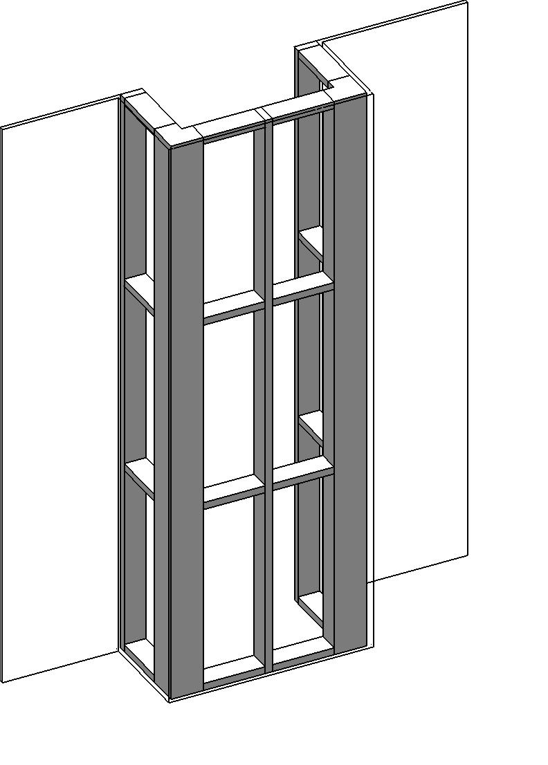
The Framing is not really my question. My question is (see attached autocad 2d drawings - non adt) how do I achieve this type of construction documentation in Revit for my floor plans and plan details and exterior elevations. The framing contractors can engineer the stud work. I'm trying to design the exterior skin of the buildings as I have done in the past using ADT, but with revit as a newbie. Which worked pretty well at this type of design. 1. So what are the approaches at managing the wall types to achieve this. Multiple variant wall types? Or can one wall be used for the main wall and another used for the brick veneer (build-outs) with it's core structure the same as the main wall? 2. Again I find that by adding an opening, that revit does not shows the sybolic dashed lines of that opening within a wall. Doors & windows are the same way. I have to draw the lines in myself. I just want to define the wall types, create my floor plan and then be able to detail the plan details at the brick base level, above coping level and at the canopy level. I know that revit can do this, but the fewer wall type styles the better. Daryl maybe some advanced wall videos could be created. Classified by type of construction and proper management of those types for multiple user environment would be great. Tilt concrete panels - footers/imbeds & connections, traditional masonry on different types of backup. Advanced lightweight curtin wall panels/ with or without veneers/or textured finishes etc. Thanks, David
|
This user is offline |
|
|
|
site moderator|||
Joined: Tue, May 16, 2006
13079 Posts
|
Looking at your plan and not accounding for the change in materials vertically, I would probably model this as 2 wall types. The main wall is masonry, then you have a single wythe on air-space (but I would not include the air-space) and a single wythe on stud. This would get you your plans and elevations but the inside line of the compound walls would be heavy and I would have to use the linework tool to clean it up. Does this approach give accurate quantities - NO - If you need that then you have to be more accurate. But this will model correctly for plans - sectios & elevations.
|
This user is offline |
|
|
|
active
Joined: Thu, Mar 17, 2005
1231 Posts
|
Excellent images David thanks. NOW we can get back to the real question of 'how can you recreate these construction documents' with revit. This illustrates a great real world situation and perfect for a set of commercial building videos. Leave this with me and I'll take a crack at it. Then we will probably need a follow up because this will get the wheels turning (not spinning) for you. Which is what you want. I wish there was a way to use a parameter to control part of a wall structure thickness?? Anyone? You can make a project paramter for walls but we need that little parameter button inside the wall structure dialog box to connect the two. I see three potential wall types (excluding vertical material changes) 1. 8" CMU This because we don't want to have to break up the wall as it follows the grid line yet changes construction. (just like they would build it) 2. Brick + 4 " Studs, 3. Brick + 1.5" Studs etc.. Not sure how I will handle the air space. Needs some testing. We can make the doors and windows penetrate the adjacent walls no problem. We can also fix your problem with the hidden lines for doors and windows. As for the wall base bump out, I will get more details and do that last. I think I will model the core masonry walls regularly and then use Massing for the rest and apply the building maker tools of 'Wall by Face' to do the exterior cladding. Massing is fun, easy and flexable. Then I am sorry to report that I will suggest using the 2d detailing tools to complate the callouts. I have visitors coming in from out of town to eat lobster, drink beer and play golf so this won't be available until next week : ) Hold tight.
-----------------------------------
.
FULL 'DOWNLOAD ACCESS' to all 850+ CADclips videos for only $150
|
This user is offline |
View Website
|
|
|
active
Joined: Sun, Jun 24, 2007
592 Posts
|
just because I can throw in 2 cents, has anyone considered wall wrapping options to get the return on the brick and stud layers in plan? seems like you could do it with 2 walls types then.
-----------------------------------
I like scooters. and motorcycles. |
This user is offline |
|
|
|
Similar Threads |
|
Need to show shadow of canopy on ground |
Revit Building >> Technical Support
|
Mon, Dec 26, 2016 at 12:30:35 AM
|
3
|
|
Back Lighting a Glass Canopy? |
Revit Building >> Technical Support
|
Thu, Jul 7, 2011 at 10:35:11 AM
|
3
|
|
half circle entrance canopy |
Community >> Newbies
|
Wed, Nov 23, 2011 at 1:46:29 PM
|
6
|
|
correct way of making canopy |
General Discussion >> Revit Project Management
|
Tue, Jun 10, 2008 at 10:21:34 AM
|
2
|
|
StoreFront Canopy |
Community >> Newbies
|
Sun, May 27, 2007 at 10:47:57 PM
|
1
|
|
|
Site Stats
Members: | 2161655 | Objects: | 23325 | Forum Posts: | 152479 | Job Listings: | 3 |
|